


MagicMike
-
Posts
162 -
Joined
-
Last visited
-
Days Won
6
Content Type
Profiles
Forums
Events
Gallery
Blogs
Posts posted by MagicMike
-
-
2 hours ago, mapper said:
Don't agree. The base map is just tuned complet the wrong way. I've done a lot of testing you want big corrections at small errorrs and smaller corrections at bigger errors.
Can you elaborate a bit please? Got an example of what kind of tables you use?
-
Fantastic, thankyou muchly
-
The actual speed sensor for the Z32 is in the gearbox, and is surfaced in the software as DI3 LR Wheel Sensor. Not exactly sure what chain of events gets the signal from the gearbox sensor to the DI. I am pretty sure the sensor goes straight to the speedo and then to the ECU (PIN 53).
When I say 'dash' I am simply displaying PC link on a screen, no CAN devices or connections other than the widebands.
I am quite sure that PC link is displaying what would be the correct speed if I have a factory diff and tyres close to stock rolling diam.
-
Hi all, not sure if currently possible, or possible in the future, but I would love to be able to apply a correction factor to the displayed speed.
I have a shorter than factory diff, which wasn't an issue previously as the speedo had been modified to display correctly (with a potentiometer I think). But I didn't consider that when I did the dash install, so now I have to guess my actual road speed.
Some kind of calc would be fantastic to allow for this, or tyre size changes etc to keep the actual speed accurate.
-
On 06/03/2017 at 4:44 PM, MagicMike said:
Doesn't look like they are connected, but wiring isn't my strong point (actually not sure I really have any strong points!)
-
Wiring diagram indicates signal, and also shield on both sides (knock sub harness and also ECU side). ECU side shield is terminated at PIN 50 on a factory ECU. Ground not connected to sensor.
-
+ another!
-
3 hours ago, CamB said:
I wondered if something like this would work if set to do page up / page down (or Q / A):
https://griffintechnology.com/us/powermate
Or perhaps one with better reviews (!)
That's pretty cool, been looking for something to use to scroll through different tabs on the pclink dash...
-
Great! Thanks again mate
")
-
Hi again everyone. I wasn't sure where to put this, so I will ask a couple of questions related to the G4+ plug in also (300Z).
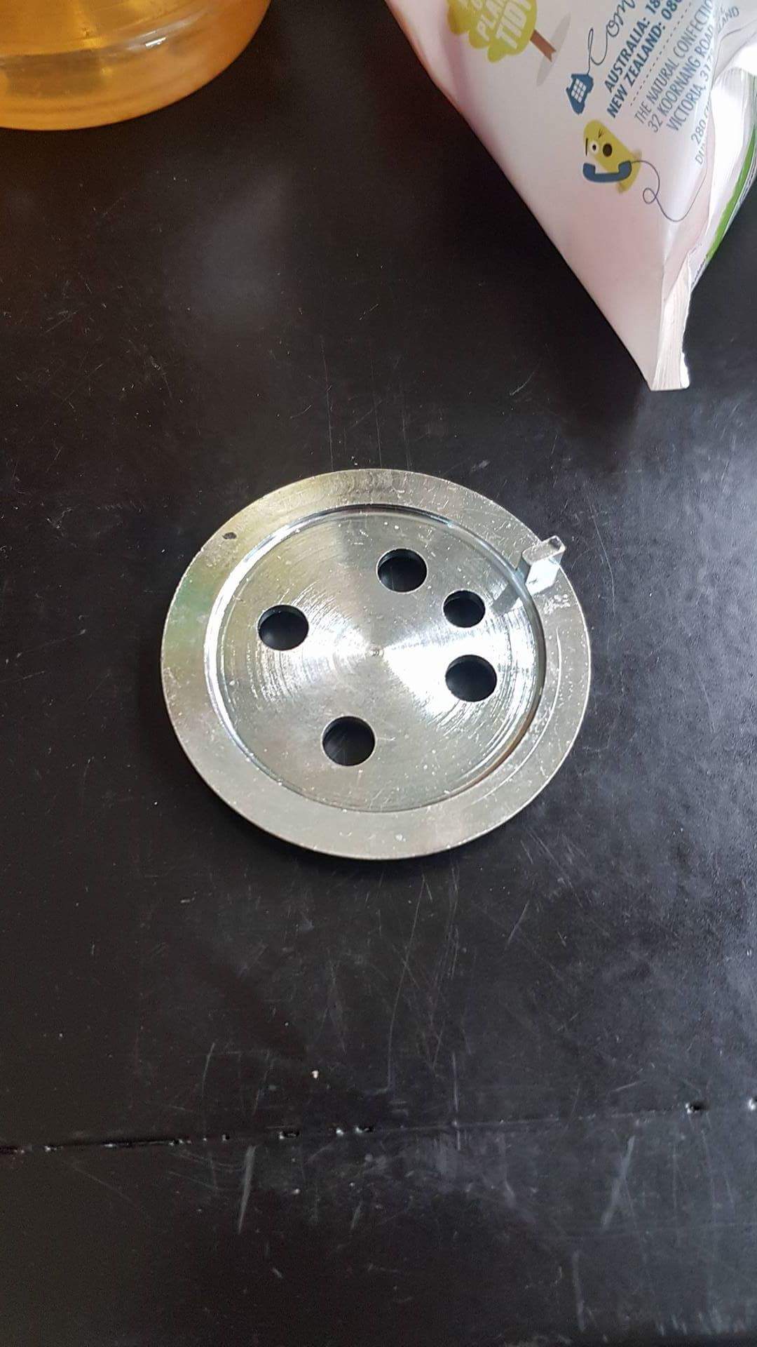
I received my ALM CAN II the other day, and I was surprised that it had a connector on the cable labelled CAN (see pic). I was expecting just a twisted pair, so I am not sure if they have actually sent me a serial jobbie accidentally. I popped the connector off and there are only 2 wires (other pic).

Have asked the question without reply as yet and I want to get cracking on this ASAP.
Does anyone have any thoughts?
Now related to the plug in, what is the best way to connect? This?
http://www.nzefi.com/product/nzefi-link-g4-g4-plug-ecu-can-cable/

Seems I have reached my attachment limit, so sorry for the tiny pic
-
Pretty much finished. First startup in car vid at the link below.
https://www.dropbox.com/s/p73ni3uusoj6t7m/car pc dash small.mp4?dl=0
![[IMG]](https://www.sau.com.au/forums/uploads/monthly_2017_11/20171024_132326.thumb.jpg.a210506ea99dd3723c8f965e5d3d084b.jpg)
![[IMG]](https://www.sau.com.au/forums/uploads/monthly_2017_11/20171024_155150.thumb.jpg.817d9f3d6b48a0582f013dce9ea040ef.jpg)
![[IMG]](https://www.sau.com.au/forums/uploads/monthly_2017_11/20171026_225304.thumb.jpg.2b9c94746b9de2a2a0eec885b03bb484.jpg)
![[IMG]](https://www.sau.com.au/forums/uploads/monthly_2017_11/20171029_140355.thumb.jpg.e18c4dd85dae63b0504d5afb628c852e.jpg)
![[IMG]](https://www.sau.com.au/forums/uploads/monthly_2017_11/x20171102_222235.thumb.jpg.c56470978069a8e89248f90fb042d18e.jpg.pagespeed.ic.QkIfMHOccY.jpg)
-
Thanks!
I have tried to make use of transients removing Accel Fuel and also TP with mixed results. Intent is to catch semi steady state cells. I also typically use 80 to 90% of active cell.
-
If anyone has time, I'd love to get a bit more detailed info on some filters and values that you use regularly, and why.
-
I just got my trigger from nz wiring yesterday. Do away with the CAS altogether.

-
How are you going to balance it? 50/50 worries me
-
1 hour ago, Miguel Silva said:
The problems that I have and some others also have are the RPM reading go a bit crazy, as an example on a ramp-run the RPMs should always climb (5400, 5450, 5500...) and on logs I see (5400, 5370, 5370, 5500...) and with the timing light there is always some drift +-2 or 3º from meed to higher RPMs. Applying max filter makes it a little bit better.
Has I've posted before it's a belt slop and or some other CAM related harmonics, I'll look for a better explanation from possibly a reliable source and post it here.
Yes I have experienced the issues myself (z32), and I now run a crank trigger and single cam sync.
Im confused as you say you have a crank trigger hut are still concerned with the stock cas disk. Sort out some cam sync solution like Brad says with aem disc or something and never look back.
-
The Z32 disk has 360 + 6. I'm a bit confused by what you are trying to achieve with this? If you have a crank sensor already why do the 360 slots cause you trouble?
-
Just a follow up to the above. I stupidly fried the original unit with reversed power. Got a new one and out of the box, the new one starts with power applied. Bonus!
-
That is interesting. My logs show the opposite. Oem in rail sensor and cont. flex sensor in the return but before the fuel cooler. Typically 2-5degs hotter on the return. Could be down to different sensor types I guess, who knows.
In other news, I test drove open loop control of the 2 pumps in parallell 2night (via SSR PWM). Worked well. Laptop went dead before i could try anything else.
-
I am in the process of doing something with a PIPO X8. It has no battery, and changing the BIOS bricks the unit, so it will need to be powered on manually each time, but that is something I am willing to work with.
It is exactly 2din screen size, but the unit itself is a weird shape.

-
No such luck having room to swing a cat like you!
Seriously considering re-plumbing the return line via the front of the car for some more room, but I am a bit nervous about putting fuel lines in the impact zone.
-
Yes, my rail is held in place with the upper plenum bolts unfortunately. Tank is steel, and I have a ducted cooler on the return line, which is great while the car is moving. My temps are highest when stopped on the side of the road looking at logs etc (haven't ventured out into traffic yet).
-
Fantastic!
-
14 hours ago, Ducie54 said:
I'm using the FP speed in open loop for the 1st pump and a 2D GP PWM table for the 2nd pump. Using injector DC% as the axis.
I haven't needed the 2nd pump just yet as Ive got 16volts to the pump.
What's the highest fuel temp you have seen?
In my current config, I have seen mid 50's. Old surge tank/fuelab setup I saw mid 60's!
It would be great to have axis configuration of the open loop FP Speed table, 3D even.
14 hours ago, Davidv said:Slightly off topic but perhaps relevant to the intentions of this thread.
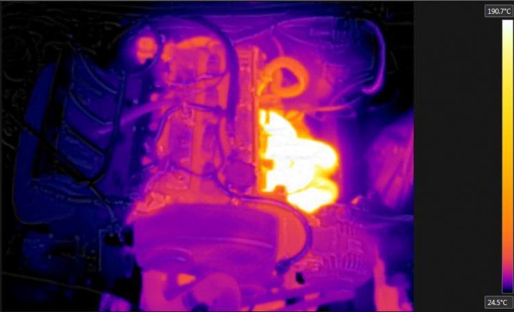
I did some tests with a thermal camera, with the fuel pump running and the engine turned off.
In this case, what heats up the fuel is/was when the fuel flows through the hot fuel rail bolted to the head, and then circulating down to the fuel tank and back through hot fuel rail again and so on.
Which is even worse when you have a surge tank to the fuel rail, which is probably why people think its the pumps making all of the heat.
If you slow down the speed of your fuel pump, and the fuel is flowing slower through the fuel rail then you're still transferring the same BTU of heat. (Half as much fuel flowing for twice the time through the hot rail)If I leave the fuel pump running with a cold engine, it took something like half an hour to increase by 5 degrees.
But with the motor running the fuel temperature increases almost immediately.
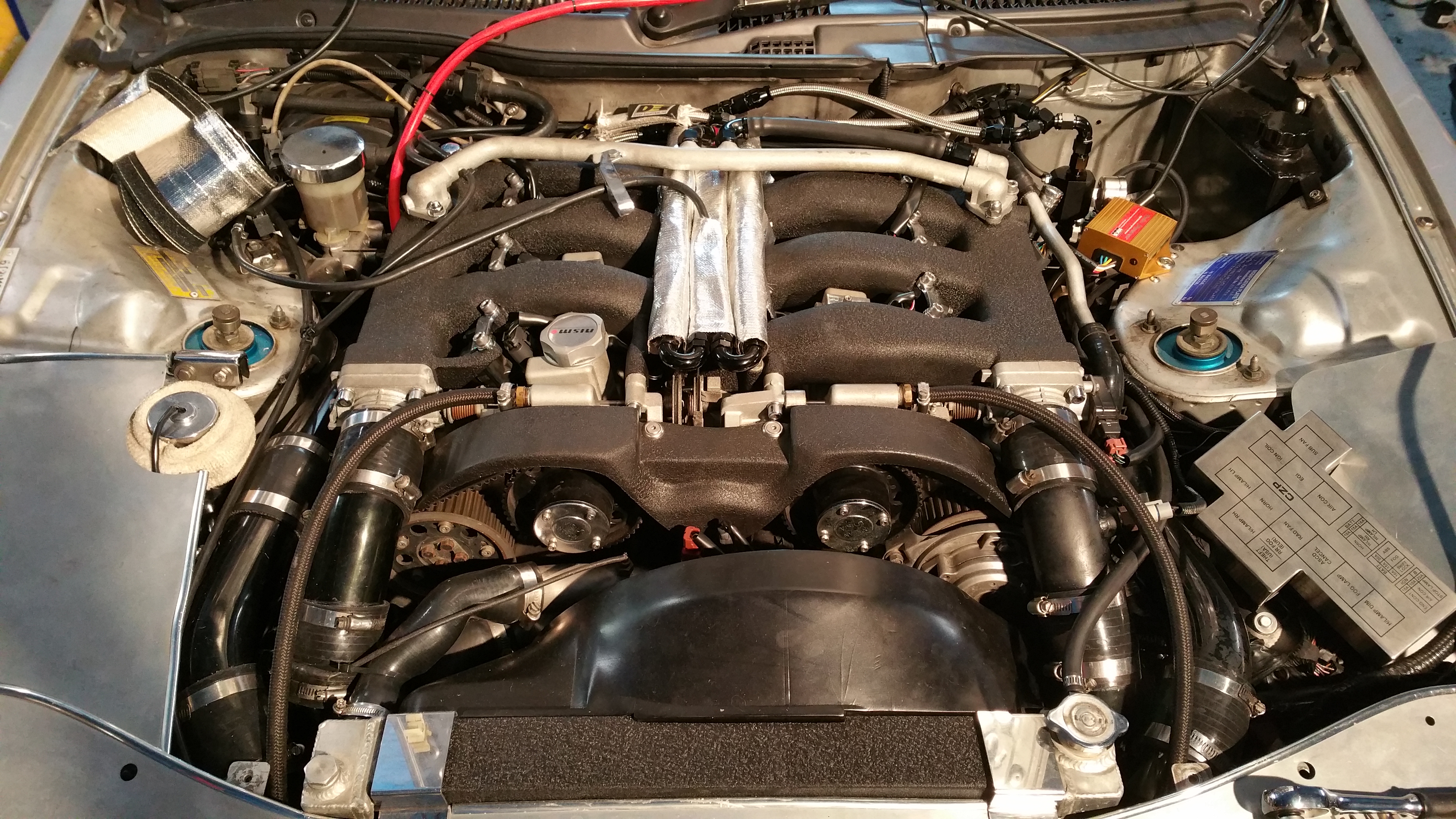
Insulating the fuel rail from the heat of the head and I never had fuel temp issues again.
Fuel rail is dark blue item near the left hand side after insulating it with thermal paint, and putting plastic washers under the bolts that hold the fuel rail to the head.
EDIT:
Found a pic of a close up of the fuel rail, you can see the hot bolts (now insulated) against the rest of the rail (darker colour)
Totally in line with this thread. I have tried nearly everything to insulate all my fuel system from everything hot (cool tubes and heat shields everywhere!), and while I have made some gains, I'm going to have to revisit isolation as opposed to insulation. I will have to have a closer look, but I don't think I can get away with inserting some washers, I fear it will raise the rail too much and unseat the bottom.

That is the general idea. Same all under the car and up the firewall etc.
13 hours ago, Ducie54 said:Mike have see the Injector dynamics PRI videos. Worth a watch if you haven't
Thanks for the link, I watched a couple last night, some good info!


![[IMG]](https://www.sau.com.au/forums/uploads/monthly_2017_11/20171024_132326.jpg.ddfa7973aa6dc3c49f3353c91be98a8b.jpg)
![[IMG]](https://www.sau.com.au/forums/uploads/monthly_2017_11/20171024_155150.jpg.7863d20f2561ba08442f85f5dd509da9.jpg)
![[IMG]](https://www.sau.com.au/forums/uploads/monthly_2017_11/20171026_225304.jpg.4c3e7ebaacfe79d4cd19a36f7ba85fad.jpg)
![[IMG]](https://www.sau.com.au/forums/uploads/monthly_2017_11/20171029_140355.jpg.3454beb94040e7393dd8554e793ca661.jpg)
![[IMG]](https://www.sau.com.au/forums/uploads/monthly_2017_11/20171102_222235.jpg.7d1055c8434ed33bb4252b96799f5084.jpg)


300Z G4+ Plug In tune file/log review
in Engine Tuning
Posted
Hi team,
If anyone is interested, I have attached a log and tune file from last night. I have since made a few changes to the VE map based on this log.
It would be very much appreciated if anyone could have a look and offer any advice as far as configuration or anything is concerned really. I don't claim to be a tuner, I probably know just enough to be dangerous, but I like to have a go myself.
Modlist is extensive, turbos, breather mods in and out, cams, top feed injectors (bosch or Xspurt 1650/1550 or whatever they are). I have retained VCT.
I have only really touched on the fuel map where I could hold with the brakes, and have done just enough WOT pulls to know it is really fat up top. Have had great struggles getting injector data that seemed to be ok.
I'm not sure why my 3500rpm column is so much heavier than the rest, but it seems it is what it likes.
Any and all feedback would be much appreciated!
Thanks in advance,
Mike
https://www.dropbox.com/s/9csf2zjdyrzue2n/coast.pclr?dl=0
https://www.dropbox.com/s/10xn3jkcf4vqvkd/Log 2017-12-14 11%3B45%3B15 pm.llg?dl=0