


atlex
-
Posts
66 -
Joined
-
Last visited
-
Days Won
2
Content Type
Profiles
Forums
Events
Gallery
Blogs
Posts posted by atlex
-
-
My oscilloscope still isn't calibrated as I don't have a regulated power supply (...yet.. it's on order!) but I have managed to get a decent signal out of the sensors.
This was with ignition and fuel - the motor was just idling.
Here's the run I got out out of the ex cam sensor.
It's showing an offset of -180mv at the bottom (calibration needed..)
p2p is probably more important here and that's close to 3.8v

in the calibration mode it shows a -0.23v with the probe shorted to its own ground - so if you wish, you could read the -180mv as being a 50mv ground voltage signal. a far cry from 0.91v :/
-
16 hours ago, Adamw said:
Can you short pin A5 to A7 with a paperclip or piece of wire and do a scope capture like that.

I put some paperclip in precisely as described. Sat at 0.91v without the engine turning, never went below 0.91v when it was turning.
Ignition and fueling were disabled for these tests.
The screenshot below is of me turning the motor over without the LG being connected for the CKP, but with the a5a7 short in.

TriggerScopeLog-ckpgrounddisconnected-a5a7shorted-startermotorturning.llgx TriggerScopeLog-groundsconnected-a5a7shorted-notstarted.llgx TriggerScopeLog-groundsconnected-startermotorturning.llgx
-
I'm working to find another car to test this ecu in.
On 8/18/2023 at 6:19 PM, atlex said:when I ran it I saw a relative offset ground voltage (0.3v) and signal voltage (1.5v) on both the g4x and the kpro having backprobed the inlet plug while running the motor.
The oscilloscope was uncalibrated (derp) so I will repeat that and get screenshots of the signal.
-
On 8/11/2023 at 12:15 AM, Adamw said:
The quickest test on your crank sensor would be to pull the ground wire out of the connector and run a temporary one direct to the ecu.
I did this to the exhaust cam sensor (trigger2) since it was easier to reach and suffering the same ground offset.
I disconnected the logic grounds in the original loom and ran a new pin to either LG1 or LG2 (the other one left disconnected)
Original signal and power to the sensors remained.
Turned off ignition and injection... results..
0.91v

trigger2 retains the same old 0.91v ground offset with the new dedicated ground. is this an ECU at fault ?
can't explain the trigger1 result though, if there's no earth wired up to it... is it earthing via the signal, or something else ?
-
did a quick check of the exhaust cam sensor plug (sensor disconnected)
I see 4.1v between the signal wire and the chassis ground/logic ground - seems wrong to me?!
I've never seen the 0.9v between the logic ground and chassis ground with my multimeter... even when cranking.
-
So the update so far:
I have a working oscilloscope!
when I ran it I saw a relative offset ground voltage (0.3v) and signal voltage (1.5v) on both the g4x and the kpro having backprobed the inlet plug while running the motor.
interestingly on the kpro I saw offset voltage via multimeter between the logic/signal ground for the cam sensors and the battery/chassis negative - 0.8v - and if I pulled the fm2/ign2 fuses this was halved to 0.4v. but on the g4x this doesn't appear and I get 0v readings.
but the oscilloscope reading was the same.
if I attach my multimeter to the inlet cam sensor (only used for vvt control - it's on DI1) between that sensor plugs ground and the battery ground I get 0v even when the engine is running.
I also went back to test the map sensor since that was noted before. 0.2v signal if the plug is disconnected, 0v if signal and signal ground are shorted - grabbed a trigger scope of this and it made no difference to the trigger signal, just saw a 0v map signal...
I've a few more tests I want to run next week when I get access to a car lift.
-
12 hours ago, DerekAE86 said:
What type of G4X is this? A wire-in model?
I would be aiming to make things better than OEM rather than working around what the OEM might have done
(in relation to sharing Sensor Grounds and Chassis Grounds)Make sure the Sensor GNDs don't have continuity to the Chassis/Engine at all. Make sure the ECU Power Ground is good to both the Chassis and Engine.
This is a plug in. I'm using the stock-ish K20A2 loom.
This loom has separate Power, Logic and Sensor grounds..
map sensor ground SG1 A11 direct
tps sensor / IAT sensor / ECT sensor ground SG2 A10 shared
fuel tank pressure sensor (unused and unwired) ground SG3 E4
CMP A (sensor VVT inlet) - signal A25
CKP (crank position) - signal A7
CMP B (sensor b for tdc aka exhaust) - signal A26
all three share the same LG1/LG2 ground(which would also be to the G101 location along with PG1/2 but even if the only ground path (I cutLG1/2 off G101), there remains 0.91v on the signal.
ECU Power Grounds are to PG1/PG2 which are A4/A5 respectively and these go to the head of the motor (G101) but I've tried different grounding points, made no difference.
I'm thinking to disconnect all the sensors using SG1/2 grounds and see what happens.
My oscilloscope is nearly ready.
-
So thank you for putting up with me so far.
I haven't hit the map sensor with the paperclip check again or done the crank sensor direct ground yet.
I've instead removed the grounding between LG 1/2 and the Motor. Per the G101 photo above it was the same place as PG1/2, I just snipped off the brown/yellow wires at a suitable point where I could reattach them with crimp connectors should I want them back.
I then proved (in as much as I can) with a multimeter that there's no other source of continuity to the LG1/LG2 wiring other than the point at which they connect to the ECU. Alas this isn't strictly true of continuities to ground itself, there's continuity to ground on the brake switch input and the vtec oil pressure switch inputs.
This made the ECU the ground for these 'logic' sensors - the two cam sensors and the crank sensor. And this made no difference to the 0.91v ground voltage offset in the trigger scope. And the signal looks no different to what it was before. Even with the sensors disconnected we saw the same offset. The paperclip grounding to signal proved that.
I'm left scratching my head as to the source, as I've literally gone against the advice and should have made it worse.
Tomorrow I'll try grounding the PG1/2 to another point but there's only 0-1 ohms between it and the battery negative.
Is the problem even real ? The new fresh loom hasn't arrived yet and I will probably get a friends garage to take on that work.
I'm going to try independently verifying the offset voltage with an actual oscilloscope. Seems like the right thing to do.
-
Cleaned up the battery-to-chassis and added more chassis-to-block and chassis-to-head grounds.
Where it looked dark on the 'G101' picture above was just dirt and that cleaned up. This indicates the LG and PG are to the same location.
Also tried pulling the crank sensor connector.
No change to the ground voltage offset.
I ran another test with the map sensor plug disconnected and saw 0.07 volts signal in the trigger scope for map signal voltage.
Riddle me that!
I've also ordered a spare used k20a2 loom since I need a way to take that out of the equation.
I could add one more ground, but I'll need to get the car up on a lift to do that. I doubt this will help.
-
So I've found the point at which LG1/2 and PG1/2 go and it's the same ground connector, the one called G101.
LG1/2 are brown/yellow and PG1/2 are pure black and those wires are all here.
I'm going to try clean it up a bit more but I'm stumped a little now. I will check if that's dirt on the connector or it could be that the ground was fried. If you look at the shade of the brown/yellow cable as it comes to the metal it's darker than it should be frankly.
I will head to a local marine chandler and buy some suitable wire to make grounding cables and redo what there is.
Time to redo the battery to chassis grounds also.

-
Tested with the paperclip shorting sig to gnd - 0.9v confirmed in the trigger scope.
-
I've done the quickest thing first since it's hot out there. I disabled fueling and started pulling connectors and taking scopes.
inlet cam disconnected was normal bad as before, 0.9v ground ref on trigger 2 ex cam
exhaust cam sensor disconnected was a mostly 3.89v on trigger 2 ex cam (!) with a few very brief drops to 3.66v
both inlet and exhaust cam sensor produced random spikey noise between 3.66v and 3.89v on trigger 2 ex cam (!)
in both cases crank sensor signal trigger 1 was mostly fine but I will try disconnecting that just to see what that produces too.
would expect to see a flat line 0v with the exhaust cam sensor disconnected and as for the noise with both disconnected.. I want to try disconnect the crank sensor too.
Onward to the wiring....


Both Cam Sensors Disconnected TriggerScopeLog.llgx Exhaust Cam Sensor Disconnected TriggerScopeLog.llgx Inlet Cam Sensor Disconnected TriggerScopeLog.llgx
-
That trigger graph was while the engine was idling and iacv running so we'd _maybe_ expect to see some change in the MAP signal, I think, although I may be reading it wrong.
Battery negative to chassis ground _appear_ to be good - I see 0-1ohm resistance between far chassis points and the battery negative and when there's current, i.e. the engine is running, this goes up to around 10 ohms. [This seemed better than another car I have]
I've been reviewing some guides on this - https://dsportmag.com/the-tech/education/how-to-avoid-and-fix-automotive-electrical-issues/ and the wiring diagrams for the EP3. I'm going to have a go with the testing of these. Will see how disconnecting sensors may clean up the trigger scope.
I see the the grounds for the Inlet, Exhaust and Crank position sensor are a bit odd in that they appear to be to the A23 LG2 A24 LG1 logic grounds which are also hooked up to a Chassis ground (I don't know why?) - will start testing the sensors and wiring for these.


-
9 hours ago, Adamw said:
But one problem I do see is the low level voltage is only coming down to about 0.9V, it should be close to 0.0V. This would suggest a ground offset somewhere between the crank sensor ground and ecu ground. The switching threshold is 1.0V so you are only a small margin away from having a problem.
Thank you. If you have any pointers to tips on identifying/rectifying this I'd appreciate it. I've got a multimeter, guessing to look for voltage between the signal ground and the sensor ground plugs ?
I'll try and address this before looking at the map signal. I could also switch to the onboard map sensor but I'd rather not.
-
Wiring is mostly stock K20A2 from the EP3 Type R - it's a CTR engine loom with some links into the original toyota harness where necessary.
I could attend to/clean up some of the earths and take another gander at the scope.
The car runs. Does anyone have an example for me to compare with ?
-
Hi Folks,
I've switched from Kpro to G4X on my K-swapped ZZW30 MR2. It's a stock A2 motor.
I'm working on the tune at the moment and I want to be sure my triggers look good.
Is the timing OK or will I need to mess with offsets ?
It's a COPS car obviously so I may need to hack something up for running a timing gun.
Alex


-
On 7/8/2023 at 1:34 AM, DerekAE86 said:
I've done similar to this without using Math Blocks.
Big Inspiration. I've now written something very similar but for the VTEC - the GP PWM / CAN AUX is a very interesting way to run this. Once I've got the ecu on the car and running I'll test it out / publish it.
-
Kpro-like VTEC Windowing - in the absence of a 'Generic Table' type function I came up with this:
Math Block 1: VTECWindowLow
Param b Map
Param b Engine Speed
a>87&b>4600
Math Block 2: VTECWindowMid
Param b Map
Param b Engine Speed
a>68&b>5200
Math Block 3: VTECWindowHigh
Param b Map
Param b Engine Speed
a>50&b>5600
Math Block 4: VTECWindow
Param a: math block 1
Param b: math block 2
Param c: math block 3
a|b|c
Then feed math block 4 as one of the parameters for the GP Output for vtec:
Param 1 : math block 4
Param 2 : ECT>69c
Param 3 : Vehicle Speed >10kph
Switch Logic: 1 and 2 and 3
Works Well!
Notes: the an oil pressure check could be added. VTSP appears to be inverted on my car.
-
Uninstalled pclink then nuked the PCLink folder in Roaming and then a reinstall and lastly loaded my saved layout and that sorted it out.
Thanks!
-
Today PCLink lost my layouts - as in, all gone. I didn't perform an upgrade or anything like that, it just decided to disappear after a (weirdly) battery change on the laptop.
I recovered the layouts from a backup so am happy with that but now the next issue is this..
All the log graphs have gone white, lost all sense of normality, and I can't change them - as in, if I try and edit the colours, or any of the choices, the choices don't stick... I press OK and it's back to white.
I've tried uninstalling pclink and reinstalling and restoring the layout and that still retains the white colour issue and I still can't change them.
What next ?
-
On 3/24/2023 at 2:17 AM, Adamw said:
I usually just put engine runtime on one axis of the IAT table for this type of correction in the past. At high IAT's add xfuel for xSeconds then fade it out over xSeconds. I think your post start table would do pretty much the same thing.
I started thinking about this setup when a friend showed me a post of one of the actual experts here (you or Andrei?) saying that the IAT fuel correction table shouldn't be used in modeled mode. I'm guessing the modeled mode is designed to use an ideal gas law internal table...
Previously my solution was to roll an IAT fuel correction table with a TPS Y axis to help boost the lower TPS zones going lean for hot start and hope that with driving the IAT came down again, but I knew that just wouldn't cut it in summer and will absolutely mess with any closed loop stuff LTT stuff which honestly handles this far more cleanly heh.
-
Just sharing something I've come up with to solve a particular condition I've seen.
I've had a scenario where I get quite a lot of heatsoak and my injectors seem to open too slowly(or something, but I did see some data on this condition on another forum) to fuel correctly so I see a lean condition for up to a minute as fuel flow cools them down again. My IAT sensor is close to the injectors so we can use that number as a factor..
I recognise a suitable closed loop solves this after the wideband is sending real data but I didn't want to run adhoc fuel corrections for IAT since those are permanent and where I live the air can actually be quite hot. And a wideband can't give adequate fuel info until it finishes warming up.. this leads us to the post-start configuration..
I've ended up with a 3d table for post-start where it's X ect and Y iat - similar to a regular post-start 2d table but with the higher IAT area seeing up to 35% more fuel put in - say 30c IAT 10% more fuel, 40c IAT 20% more fuel, 50c IAT 30% more, up to 35% at 60 IAT
Closed loop set to come on after 25 seconds, post start hold time 25 seconds with a 5 second decay.
-
one of my tricks for pc logging at the full 40hz is to have another view that's empty bar a few key stats like knock count and iat/ect.
if I set it to pc log, I then switch to that view to get the maximum possible logging rate during a session, then switch to the more complex views to do analysis.
i7-4650U CPU @ 1.70GHz 2.30 GHz + 8gb ram. nothing to scream about.
-
You can set it to pull out the ignition retard / added fuel over time also, I think with the normalization config ?
if it gets to the area that had trim and doesn't see knock it can pull out the added trim over time that way it keeps in the trim tables the amount needed to pull the knock back below the threshold. below example shows the trim getting gradually walked back by that setting.
I recommend checking your log for knock count and the trims so it's obvious what's going on while getting the tune right. Just check that as a process...
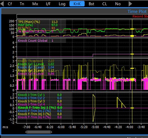
log layout with


K20A2 Trigger Scope Check Please
in G4x
Posted
I'm under no pressure to complete tuning so would rather arrange connection now than later. There's a ticket open with tech support. I'll pass my address details over on that and then proceed to decant the ecu from its case.
Alex