


Richard Hill
-
Posts
319 -
Joined
-
Last visited
-
Days Won
14
Content Type
Profiles
Forums
Events
Gallery
Blogs
Posts posted by Richard Hill
-
-
Thunder would be great. Loads of spare aux outs and inputs, and dual lambda too. You also get built in ECU hold power control. I have a 3uz which I will run with my thunder.
Just not sure what car it's going in yet !
-
-
You can't run a gauge from the CAN Lambda. I have driven gauges from a PWM AUX out before but it would require careful calibration of the duty cycle and frequency vs displayed value (AFR/Lambda)
-
Hopefully an LS1 coil expert will step in, but yes that's how I would wire it ( I am more familiar with 3 pin k20 coil packs, and 4 pin Toyota coil packs which we leave the feedback pin unconnected)
-
Post edited due to innacuracy.
-
27 minutes ago, mrharvey1301 said:
Hoping i could get some clarification on the following,
currently in the process of wiring a g4+ fury, aim strada 1.2 dash and LS1 coils
1st query is on the signal ground for the LS1 coils,
can i wire the signal ground and the power ground both to the engine block? as per picture? Not sure if the sensor ground is required to pass back into the ecu
I wire power ground to a ring terminal connected to an inlet manifold bolt straight into the head, Signal grounds must go back to the ECU (wherever possible)
2nd query is on the aim strada can wiring
on the aim wiring i have can 1+ and can 1-, can i wire these into can 2 l and can 2 h on the b plug and program to talk with the can setup in g4+ software? i figured this was easier than getting the correct plug for the link to wire into can1?
Wire the CAN 2 high and low on the ECU to the ECU+ and ECU- on the Aim Dash loom.
3rd query
the 5v supply for generally sensors is there a limitation to how many sensors you can run off this 5v supply? i've noted from factory it is spliced into 2 wires, if i run 10 sensors that require 5v feed for example do i just splice this 5v feed 10 times?
usually no practical limit if you are using factory sensors. If you are making your own potential dividers, select resistors which minimise current draw but give a high enough signal to noise ratio. You can check the +5 Volt supply, by going into runtime values in PClink (F12) and look at the ECU status tab.
Does the same go for the green sensor ground wire and seeing as A/B plug each have their own grounds are the sensors required to be grounded relative to the plug they came from?
I wire the sensor grounds into pin 24 on the A plug and pin 22 on the B plug. It is good practice to keep the sensor grounds close to the input associated with them. Use pin 7 on the A plug for trigger grounds, and pin 17 on the B plug for knock grounds.
New to using link and wanted to confirm rather than assume
Hope this helps,
Richard.
Appreciate any assistance

-
https://shopbhp.com/products/8-channel-egt-to-can-module-works-perfect-with-link-ecu
These work great over CAN with link ECUs, with the advantage that you can run 4 EGT in the primaries and a post turbo EGT for turbo protection
-
Hi, yes this worked well for my application, what is your exact application and what divisor are you trying to achieve ?
-
Looking at the log file posted for the speed, there seems to be a frequency doubling artifact. This might be caused by a double edge on each transition causing the ECU to randomly see twice the frequency. possible issues could be compromised grounding (old loom with oxidised ground rings maybe?), a low pass RC filter might help.
HTH,
RIchard.
-
Yes, you can have a boost target for each gear, implemented with either open loop or closed loop.
and yes, an accelerometer can be installed. There are plenty of single or multi axis ones available and they can be powered from the +5 volt supply available on all Link ECUs and input to an analog voltage.
This 3 axis one can be powered from the +5V :-
https://www.adafruit.com/product/163
HTH
-
It looks like they've reversed the wires.
-
If you mean the A or B loom then yes , just push the white tag on the side of the connector until it clicks, and then pull the cable out the back with the pin. When you've finished adding or removing wires, push the double white tags on the other side to lock.
HTH
-
Ethrottle1 is recommended to be on aux 9 and 10 on a wire in ECU, as these are powered by pin 5 on the b plug and thus allow indepenant relay control of the power ( allowing the ECU to shut down the ethrottle for safety). For some reason, the plug ins don't use this strategy...
-
To control a stepper motor you need aux 5,6,7 and 8. So I believe any G4+ with at least 8 aux outs will work. Other idle valves don't have the same constraints.
HTH.
-
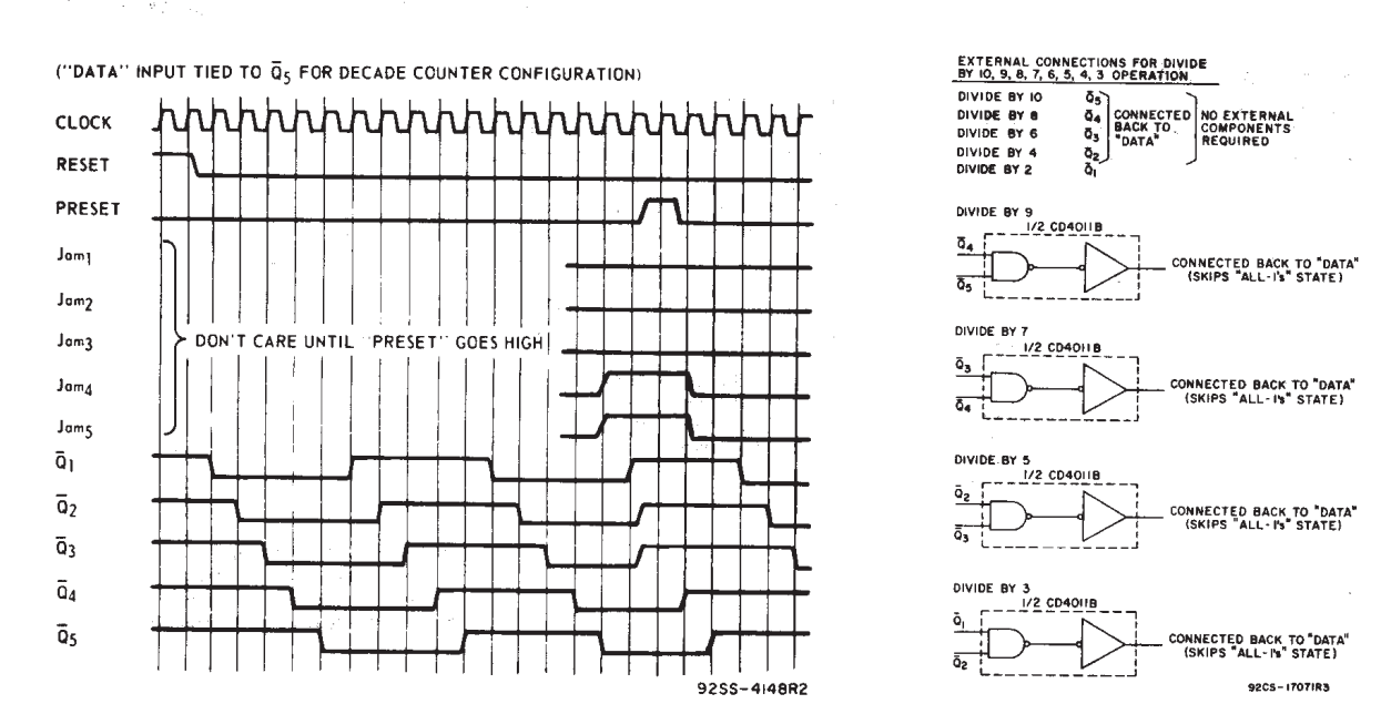
Another way to work around the missing inputs on the Thunder (or to divide an input frequency down on other ECUs) is to use a CMOS 4018 IC. No external components required and can be powered from the ECUs +5 Volt supply. To divide by 10, the inverted Q5 output is fed back into the data input pin. I used this last week to divide by 8 on a fury (I fed back the inverted Q4 pin to data). It is possible to hide this in a connector rubber boot too.
Hope this helps,
Richard.


-
Another way to work around the missing inputs on the Thunder (or to divide an input frequency down on other ECUs) is to use a CMOS 4018 IC. No external components required and can be powered from the ECUs +5 Volt supply. To divide by 10, the inverted Q5 output is fed back into the data input pin. I used this last week to divide by 8 on a fury (I fed back the inverted Q4 pin to data)
Hope this helps,
Richard.
-
On 10/10/2018 at 3:43 AM, Simon said:
Likely the voltage output from the sensor is still too low to register. The faster you spin the wheel the bigger the output will get and I suspect eventually give a signal.
Our digital inputs can already accept a VR sensor input directly, there should be no need to a VR conditioner unless it has a very low voltage or something?
A VR conditioner will detect low voltages more accurately than a TTL input...
-
I needed a vr sensor converter for my lotus , I used one of these, worked well, still fine 5 years later.
http://www.jbperf.com/dual_VR/v2_1.html
Monit also do a converter, but I haven't tried it.
http://www.monitrally.com/sensors/home.html
-
this info taken from the Link help file :-
The 'Transmit Generic Dash' mode sends out a range of common parameters, it is useful for dashes that are able to have a custom configuration. The parameters that are sent are in the table below.
Setting up the Link ECU:
1. Open the CAN Setup window (PCLink > ECU Controls > CAN Setup) 2. Select the CAN module to be used 3. Set the Mode to 'User Defined'. 4. Configure the Bit Rate to match what the dash requires. 5. Select a spare CAN channel. 6. Select 'Transmit Generic Dash' from the Mode drop-down menu. 7. Set the CAN ID to match what the dash expects. 8. Set the Transmit Rate to 20Hz or what the dash expects. 9. Make sure no other CAN channels are configured on the same CAN ID as the Generic Dash channel. 10. Click Apply and then OK. 11. Make sure a Store (F4) is performed. Setting up the Generic Dash:
1. The dash will need to be configured to match the data layout in the tables below. All parameters are sent as 16 bit unsigned numbers, with low byte first. Some parameters must be multiplied or offset (constant value added) to get the correct calibrated value. The limits flags are sent through as a bit field (described below).
Data 0
Data 1
Data 2-3
Data 4-5
Data 6-7
Frame 1
0
0
Engine Speed
Display (RPM) = Raw
Range = 0 - 15000 RPM
MAP
Display (kPa) = Raw
Range = 0 - 650 kPa
MGP
Display (kPa) = Raw -100
Range = -100 - 550 kPa
Frame 2
1
0
Barometric Pressure
Display (kPa) = Raw * 0.1
Range = 0 - 200 kPa
TPS
Display (%) = Raw * 0.1
Range = 0-100%
Injector DC
Display(%) = Raw * 0.1
Range = 0-100 %
Frame 3
2
0
Injector DC (Sec)
Display (%) = Raw * 0.1
Range = 0 - 100%
Injector Pulse Width (Actual)
Display (ms) = Raw * 0.001
Range = 0 - 65 ms
ECT
Display (deg C) = Raw - 50
Range = -50 - 205 deg C
Frame 4
3
0
IAT
Display (deg C) = Raw - 50
Range = -20 - 205 deg C
ECU Volts
Display (V) = Raw * 0.01
Range = 0 - 65 V
MAF
Display (g/s) = Raw * 0.1
Range = 0 - 6500 g/s
Frame 5
4
0
Gear Position
Display (gear) = Raw
Range = 0 - 6
Injector Timing
Display (deg) = Raw
Range = 0 - 719 deg
Ignition Timing
Display (deg) = (Raw * 0.1) - 100
Range = -100 - 100 deg
Frame 6
5
0
Cam Inlet Position L
Display (deg) = Raw * 0.1
Range = 0 - 60 deg
Cam Inlet Position R
Display (deg) = Raw * 0.1
Range = 0 - 60 deg
Cam Exhaust Position L
Display (deg) = Raw * -0.1
Range = -60 - 0 deg
Frame 7
6
0
Cam Exhaust Position R
Display (deg) = Raw * -0.1
Range = -60 - 0 deg
Lambda 1
Display (Lambda) = Raw * 0.001
Range = 0 - 3.000 Lambda
Lambda 2
Display (Lambda) = Raw * 0.001
Range = 0 - 3.000 Lambda
Frame 8
7
0
Trig 1 Error Counter
Display (counts) = Raw
Range = 0 - 255
Fault Codes
Display (code) = Raw
Range = 0 - 255
Fuel Pressure
Display (kPa) = Raw
Range = 0 - 6550 kPa
Frame 9
8
0
Oil Temp
Display (deg C) = Raw - 50
Range = -50 - 205 deg C
Oil Pressure
Display (kPa) = Raw
Range = 0 - 6550 kPa
LF Wheel Speed
Display (kph) = Raw * 0.1
Range = 0 - 1000 kph
Frame 10
9
0
LR Wheel Speed
Display (kph) = Raw * 0.1
Range = 0 - 1000 kph
RF Wheel Speed
Display (kph) = Raw * 0.1
Range = 0 - 1000 kph
RR Wheel Speed
Display (kph) = Raw * 0.1
Range = 0 - 1000 kph
Frame 11
10
0
Knock Level 1
Display (units) = Raw * 5
Range = 0 - 1000 units
Knock Level 2
Display (units) = Raw * 5
Range = 0 - 1000 units
Knock Level 3
Display (units) = Raw * 5
Range = 0 - 1000 units
Frame 12
11
0
Knock Level 4
Display (units) = Raw * 5
Range = 0 - 1000 units
Knock Level 5
Display (units) = Raw * 5
Range = 0 - 1000 units
Knock Level 6
Display (units) = Raw * 5
Range = 0 - 1000 units
Frame 13
12
0
Knock Level 7
Display (units) = Raw * 5
Range = 0 - 1000 units
Knock Level 8
Display (units) = Raw * 5
Range = 0 - 1000 units
Limits Flags - Refer bit field definition below.
Limits Flags Definition
Bit
0
RPM Limit
1
MAP Limit
2
Speed Limit
3
Maximum Ignition Flag
4
Anti-lag Ignition Cut
5
High Supply Voltage Limit
6
Overrun Flag
7
Traction Limit
8
Low Supply Voltage Flag
9
Launch RPM Limit
10
Wakeup Flag
11
GP RPM Limit 1
12
CL Stepper Limit
13
GP RPM Limit 2
14
EThrottle Limit
15
Cyclic Idle Active
Hope this helps,
Richard.
-
If you install the software and connect the ECU , once online with the ECU the map will automatically load. Then, look down the left hand side and expand the analogue inputs tree. Have a look at the an volt 5 function and see what it is assigned to. That might shed some light on the fault. Also, there is a drop down menu to see the fault codes.
-
24 is An V5 Signal Error
-
Also, without an arm switch, idle speed control would be disabled with the handbrake on. Not so important on a race car maybe, but unwanted on a "road" car.
-
More like this:-

On the DI you have selected, turn pull-up on, and On level = low. The switches are effectively a logical AND
-
You can do, or you could wire the arm switch in series with the activation switch, wire the other side of the activation switch to ground and turn the pull-up on. That way you won't disable your idle speed control etc. when you want to use the handbrake normally.
Hope this helps,
Richard.


Hayabusa turbo
in G4+
Posted
I use USB over wifi for controlling my ECU remotely (I plan to install the Link ECU in the boot next to the engine so no long USB wires). I bought one of these from amazon which work great and are cheap :-
https://www.gl-inet.com/products/gl-mt300n-v2/
The hardware then needs reflashing with the virtual USB software:-
https://www.virtualhere.com/hardware
Powered with a 12V micro USB adapter, this gives you USB over WiFi, which should be significantly longer range than bluetooth. The Virtual firmware is available on a few different platforms so it may be possible to extend the range even further.
HTH,
Richard.