Dave Kriedeman
-
Posts
1,365 -
Joined
-
Last visited
-
Days Won
48
Content Type
Profiles
Forums
Events
Gallery
Blogs
Downloads
Everything posted by Dave Kriedeman
-
Thanks Thom, good luck with the tuning and remember, anytime . Regards Dave.
-
Thom, what is the capacity of this engine in cc's Regards Dave.
-
Hi Thom, Dave from ViPEC forums, how have you been. Load the PCL file on this forum or PM it if you don't want others to see it. Regards Dave.
-
Hi Bob, this is an easy request, can you please send your pcl file and I will set it up for you. Regards Dave.
-
Hi Richard, can you please attach your PCL file for inspection. Thanks Regards Dave.
-
When you say put to ground you do mean sensor ground don't you.
-
Hi Kuuno, you are correct the diagram does show that the pressure sensor is a variable resistor as per normal, not a switch. You will need to contact your supplier to get the specs as far as voltage or resistance : oil pressure to be able to make a CAL file to suit. You need to also go into analogue inputs and down the bottom go to fault settings and set your low and high volt warning settings , set minimum to 0.00volts for now. If you cant get the specs the other option is to put a multi meter across the pins and use a compressor and regulator set the pressure regulator at say 10 psi, and test ohms, set to 20 psi, test ohms etc all the way to say 100 psi or KPa equivalent if you wish. This way you can build your own CAL FILE for the sensor. Hope this is of some help. Regards Dave. Â
-
Hi Alex, we have 2 options then. One is to find why the ECCS Relay is staying active. The ECU turns the ECCS RELAY on by applying a ground to the ECCS RELAY coil, the other side of the coil is supplied 12 volts positive through the ignition circuit. Are you able to wire up another ignition relay to control the ECCS relay. I have set up an alternative power source schematic for you to try, it is the one obviously with the second bosch relay added. Regards Dave.
-
Hi Alex, can you locate and disconnect the ECCS relay while the engine is still running with the key turned off. Regards Dave.
-
Hi Sutkale, your trigger 1 will not drop below 0 volts as the reluctor interface converts the RELUCTOR AC SINE WAVE to a DC SQUARE WAVE. As you can see by your scope trace. It also appears that you have a very small glitch in your trigger 2 shown in the scope trace also. So now are you saying that you can load run the engine to 9000 rpm plus without issues except the trigger error count goes up. Have you checked on the dyno with a timing light that the commanded ignition timing by the ECU is the actual ignition timing. Regards Dave.
-
Hi, I could post up a generic setup, but doesn't mean it will suit your application. PM me your PCL file if you don't want it on the site. I am sick at present so I will get to it as soon as I am up to it. Regards Dave.
-
Hi GSAB, this engine in the video was fitted to a 19 foot LAB SPORT HULL. Dave Bush in the US does similar engine set ups and they make around 400 - 450 HP. Maximum RPM was around 8000 -9000 rpm from memory. I got it running and setup the individual fuel trim etc controlled via the EGT inputs but the owner ended up selling the Hull and as far as I know the engine is sitting in his shed. These little hulls with that type of HP would be suicidal. This boat was for water ski racing (MOC CLASSS, MOC = MODIFIED OPEN COCKPIT). Regards Dave.
-
Hi, post your PCL file up and I will set it up for you. Regards Dave.
-

Help FJO Wideband setup V88 and flexfuel sensor.
Dave Kriedeman replied to AXA's topic in ViPEC V Series
Hi, contact me on [email protected] Download free version of Teamviewer or download from my website www.protuningcairns.com under the remote tuning tab. I will be able to sort you out. Regards Dave. -
Hi, so you have set the dip switches to suit R32 /33 GTSt , not GTR. If you have set the dipswitches correctly then your  ECU is being back fed through a power source, such as a dodgey relay connection or other device , turbo timer or similar. Unfortunately you will have to back trace the wiring loom and see where the power is coming from. Regards Dave.
-
Hi , the NGK AFX wideband is a good little meter It is all you need as it comes with everything in the kit. You just need to wire the analogue output voltage wires to an analogue volt in and sensor ground at the ECU. You then just select the analogue volt channel on the ECU you connected the NGK AFX to and select, WIDEBAND NGK AFX Regards Dave.
-
Hi Bob, we would need to know what conditions you would like the boost timer to be activated and what sort of percentage increase you are after. Regards Dave.
-
Hi , Well for a start he has the boost control setup as CLOSED LOOP, however he has none of the PID 's setup for closed loop to function correctly. Is this some form of rally or competition race car that warrants having anti lag setup. Your PCL file also shows DI 1 as active which will make your low boost table active. Normally I setup low boost to be active without any input and high boost to be active once a digital input or similar activates it. These are just quick observations I have made that require addressing before any further assistance should be needed. Regards Dave.
-
Trigger options for Mitsubishi 3000GT/GTO w/ i88
Dave Kriedeman replied to 180sxv's topic in Vi-PEC i Series
Hi 180sxv, See if any of these settings help. Regards Dave. (Thanks HIC).

-
Trigger options for Mitsubishi 3000GT/GTO w/ i88
Dave Kriedeman replied to 180sxv's topic in Vi-PEC i Series
Hi 180sxv, I am sure we should be able to come up with a solution for this engine. Sorry but I must take medication now, this will render me useless, so I will assist in this tomorrow. Regards Dave. -
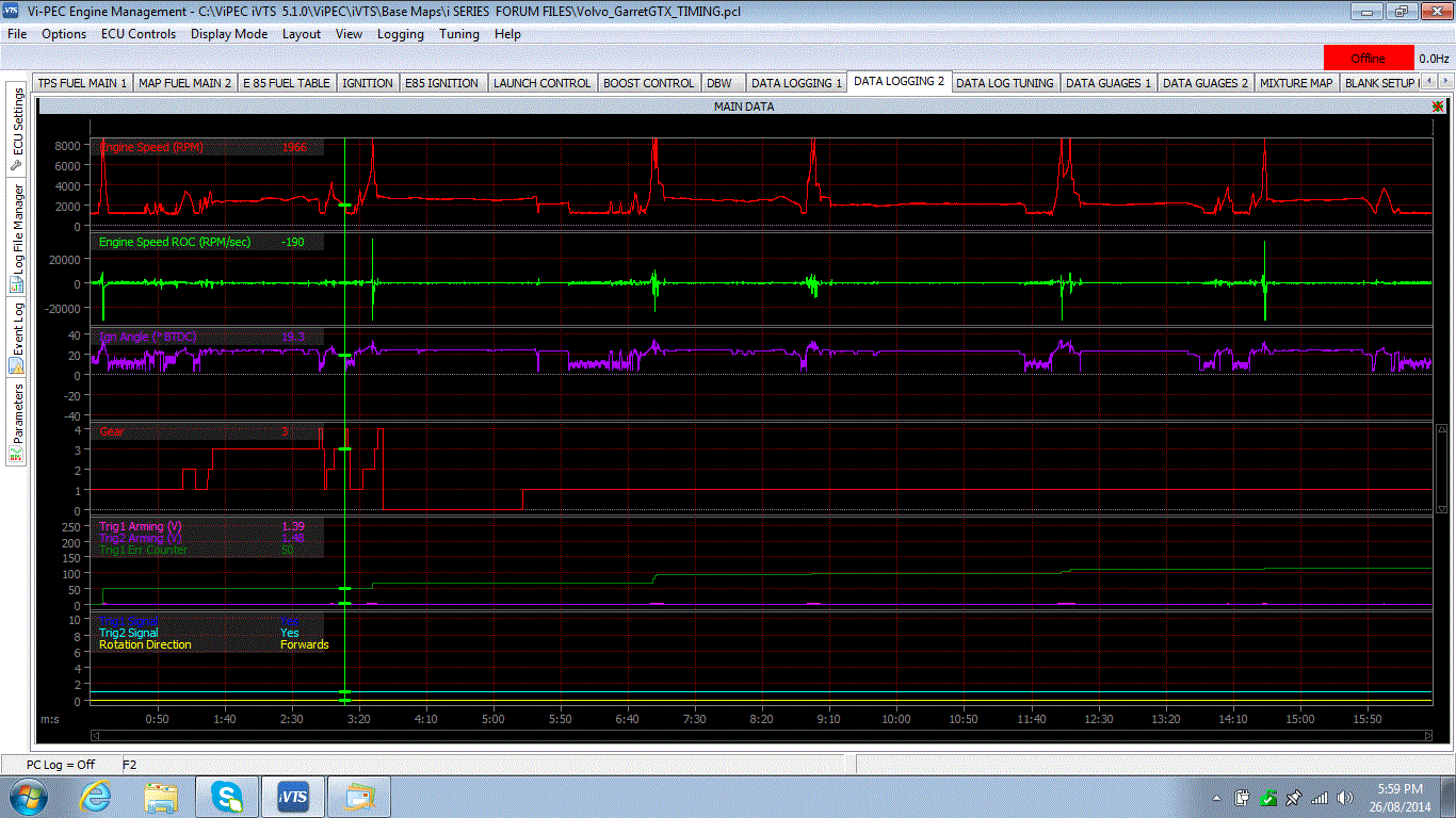
Hi, yes that is the precise reluctor interface I was talking about, they work very well. You need to try the resistor or the reluctor interface. Looking at these logs are very confusing, rev limiters cutting in for no obvious reasons unless an RPM spike occurs to quick to capture in the log. There is lots of data that doesn't make sense to me, other than trigger issues, which trigger 1 and 2 stay present the whole time. I still think you should change the arming voltage, fit the resistor or the reluctor interface. If none of that fixes it , I think I may have to pass this one onto Ashley. Strange stuff, but I never dug into my issue to deep I just fitted the resistor and all was good. I have also added small notes to the bottom right hand corner of screen shot 2 and 3. Regards Dave.


-
Hi, in my application I ran the 1.2 k ohm resistor inline with the trigger positive wire to the factory ECU. I made sure the trigger 1 +ve wire for the V88 was joined to the reluctor wire before the resistor That way the signal to the factory ECU was reduced and the signal to the ViPEC was stronger. The resistors you stated you used are far to high in impedence. You may find that a value of 650 ohms suits your setup. It is a trial and error thing, unfortunately. Before I got it correct, it would even through a rev limit warning when trying to start the engine, cranking it over the signal would be that corrupt that it would activate the rev limiter. As suggested in my previous post a reluctor interface is your other alternative, sine wave in digital square wave out, nice and clean. Just go to your local electronics shop and buy $10 worth of mixed resistors, you should get a few thousand of them for $10, I definitely did not get any email from you with a data log. [email protected] Regards Dave.
-
Trigger options for Mitsubishi 3000GT/GTO w/ i88
Dave Kriedeman replied to 180sxv's topic in Vi-PEC i Series
Hi, do you know the standard trigger patterns at all. Tooth counts, type of sensors used etc. ViPEC ECU's are very flexible with setting up triggers, sometimes minor modifications maybe required. I appolagise for not being familiar with the engine to this degree, however some basic info should get us underway. Do you have access to an oscilloscope to capture the standard trigger patterns. Is your engine a V6 twin turboed. What is the engine code, EG: 4G63 for EVO Regards Dave. -
Hi , I have attached a screen shot of my customers car I had the same issues as you with and also a screen shot of your engines statistics. See anything similar. Regards Dave.


-
Hi, my email is [email protected] I lowered the light load timing values in your main ignition timing table in case of crankshaft acceleration, deceleration issues by running the ignition timing so high within short rpm changes, (similar to cranking an engine with over advanced ignition timing, the cranking rpm goes fast then slow etc) but with the engine running as I notice in your statistics you also have had a few knock events. Under the triggers setup can you try using a higher rpm filter than 1- default. Also in your statistics it shows maximum engine speed as 14 952 rpm, I can tell you in all honesty, I have had all these exact same symptoms on a customers Supercharged V8 with V88 I had to share the mag reluctor trigger between the factory ECU and the V88, to keep the tacho etc going due to CAN BUS. I had to bias the crank trigger towards the V88 to run the engine properly, I had to do this using a resistor (1.2 K from memory)the other option would be to use a reluctor interface (converts sine wave to square wave), I had issues with excessive rpm readings which would activate the rpm limiter constantly and would also cause the vehicle tacho to play up or not work at idle. You have 1586 counts of hitting the rev limiter, now I bet they are generated via the trigger issue, not actual rpm achieved. I would have these exact issues until I got the correct biasing resistor and raised the trigger arming voltages. Regards Dave.