


wastegate
-
Posts
113 -
Joined
-
Last visited
-
Days Won
2
Content Type
Profiles
Forums
Events
Gallery
Blogs
Posts posted by wastegate
-
-
Personally I think Adam and the team does a wonderful job of helping people get their shittas running.
In fact I've seen a number of times Adam (sorry to single you out) has gone above and beyond to help.
You have to remember that these guys (non gender version) make and support the ECU. Getting the engine and systems working with the ECU comes down to who is putting in the numbers into the ECU. It's not on Link to get it running and tuned for you.
Some people keep bring up this whole thing about them feel abandoned on G4+. It's EOL, new version now with better features and faster CPU. It would be like complaining to *insert brand* management that a 10 year old laptop can't do Machine Learning or run multiple VMs. I was a little bit on the same thought when the G4X was released. But then you look at the features of the G4X and realise it's better in so many ways. Nothing wrong with the G4+, the X is just more.
I'm sorry you have had such a hard time with it. I spent 10 years in L1, L2 and L3 support before consulting for a multinational enterprise computer company, support is hard when you don't have the whole picture. You feel guilty about asking for more information, but what people don't understand is the more info you get, the better idea that support person has of fixing the issue first time for you.
- toddhar2003 and dx4picco
-
 2
2
-
Hey Guys,
I've just upgraded from a G4+ to a G4X TALTX and I'm just installing G4X PCLink EN 6.19.65. However, running into an issue were it fails to start.
Errors in a dialog box saying FTD2XX.DLL is missing. This is in a Windows 10 20H2 Virtual Machine on VMware Workstation 16.1
Uninstalling and installing 6.18.44 works fine. -
Ok, great thanks Adam
-
Hi Guys,
First up I know it's not officially supported by using this ECU with different engines like the 2J. So really just after some verification I'm looking at an issue or just a ghost.
I have a IS300 with a 2JZGTE from an Aristo, being controlled by the Altezza TALT+ PnP. Header was repinned to suit the TALT+.
Now, it's been tuned and working great for over 2 years now. But just this week I've had an issue with the AP(sub) cutting out and causing error counts to go up until it hits 100% and shuts off the ethrottle, luckily the Toyota throttle has a manual bypass over 90% to limp it home. To me looking at the logs, the voltages on the AP(sub) are dropping to 0V as AP(Main) goes up. Seems like a dyeing AP sensor. Anyway that is the background to by question and weirdness I've found that I wanted to clarify.
This is pulled from the pclink help
"Main and Sub Signal OrientationMost dual APS sensors will have an output voltage that spans the full working range of throttle plate or pedal movement. However, on some applications one sensor will span the full working plate range while the other will ONLY read up to about 70%. APS(Main) MUST be assigned to the signal that changes over the full working range and the other signal assigned to APS (Sub). Under no conditions should the orientation and these two signals be swapped."
Now, the Toyota throttle is one of those other sensors. The Toyota service manual lists the following voltages.
VTA = TPS
VPA = APS
VTA - 0.4-1.0V to 3.2-4.8V
VTA2 - 2.0-2.9V to 4.6-5.1VVPA - 0.3-0.9V to 3.2-4.8V
VPA2 - `1.8-2.7V to 4.7-5.1V
On the Altezza header pinout, these live on the following pins
VTA - O23
VTA2 - O22VPA - O20
VPA2 - O19
These are then assigned the following fuctions in PCLink with the Altezza map.
VTA - O23 - ANV6 - TP(Main)
VTA2 - O22 - ANV5 - TP(Sub)VPA - O20 - ANV3 - AP(Main)
VPA2 - O19 - ANV2 - AP(Sub)
Now from the help file, it says that whatever signal changes over the full range should be AP(Main).
However it looks like my AP(sub) is the one going over the full range..
But looking at my voltages and what is specified in the service manual, it is correct.
I've attached a couple of screenshots and a log and map for reference.Any advise or clarification is really appreciated.


Can't attach the log file sorry.
Will host it on google drive and share.Google Drive link to log
https://drive.google.com/file/d/11YA7QZDnWATpjdG04AwHa7qLZF9MIMsG/view?usp=sharing
Google Drive link to map
https://drive.google.com/file/d/1bn9Su8snS93D7RcXPNaGVwa0Py9PbYbX/view?usp=sharing
-
Update, HGM fixed the firmware and now have gear change request.
Thanks Adam on the torque reduction strategy, works a treat. Just need to fine tune it. I've reduced the IGN trim retard a little as I don't have 20 degrees of timing in some spots and it's getting retarded too much and seems to spike boost.
-
Thanks Adam! Might just do this cheers
-
Just to update, as things get confusing, managed to capture some data. Still working on getting the shifts transmitted but it's certainly in HGMs court now, likely need a input shaft speed to the controller as well to know when it's starting the shift.. They wrote a custom firmware to bypass this but still not getting anything on the shift.
I am getting the following though which just shows something is getting through.
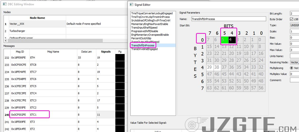
Using Receive CAN ID 217055747 (CF00203) I got from Guy @ HGM
Start Pos 5, Width 2, LS, Unsigned = Torque Convertor Locking Up
Start Pos 7, Width 2, LS, Unsigned = Gear Engaged (Shifting from P to D etc)From the data HGM supplied, looks like the Shift should be on Start Pos 3 in the Link. Not logging anything on that bit so will see what HGM come back with. They have been more than helpful to try and get it working.


-
Hi Guys,
Do you know if the CAN-MPX translator Zac designed on the TALT+ has the Cruise Light programmed into the logic? So we could add cruise light to the CAN2 Transmit Frame?
Looks like Cruise Control Light on the combo meter is at 0xD2 Byte0 Bit1 on the MPX. Kinda hoping Zac programmed it already in there and it has a CAN address reserved. -
Thanks Adam, gave it a go, no changes in state with those settings on gear change.
-
Map attached Adam?
-
Hey Adam,
I gave Byte 3 a go on both ID 217055998 and 15729152 but didn't get anything during a gearchange. I also tried Byte 11 for giggles on both IDs and nothing as well. I've attached by config and log just incase you would like to see it. But will reach out to Guy @ HGM and see if they can help too.
Cheers
Log 2020-10-4 12;12;09 pm.llg Scott's Map 07052019 - Flex Tune - Nick edit 04102020 - cold start better - new VVTI map WIP - Elite Gauge CAN - Cruise Changes - base fp 3bar - Accel Enrich - Idle Ign - IAT Fuel off.pclr
-
Thanks Adam, will give that a shot.
In regards to the filtering and units for the accelerometers, is that something the G4X can do? -
Hi Guys,
Need a little help setting up the G4+ to receive some data from a Compushift Transmission controller.
Adam you helped me with this through facebook, but didn't seem to receive anything, so wanted to make sure I'd done it right or we have the right settings.
In the facebook post you gave me the following settings
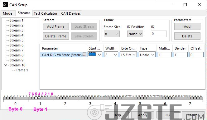
But using these settings I didnt get anything received on CAN DIG #8
Now I had a look at the HGM Compushift Wiki and they have the J1939 CAN spec in Excel format.
The CAN function I want is
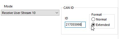
Looking at the ID, translating the HEX to dec is 15729152. So is this the correct ID or 217055998? Also having trouble understanding/translating the Signal Byte and Bit.. See you have overlay-ed the numbers for it but how come it seems to go backwards? If somethin in J1939 was on Byte 2 Bit 2 Width 2 would that be Start 21?
Also the TCU has accelerometers (X,Y,Z) and also available on CAN. Is it possible for the Link to capture and log these?
Thanks greatly in advance for any advice.
-
On 9/27/2020 at 12:17 PM, juanv08 said:
Hello everyone,
I have the Panicwire/Xcessive Manufacturing link ecru for the 2002-05 is300 Auto to manual. I am running a modified stock 2jz harness to a 1jz vvti w/ ETCSi. Car runs fine no problems with drive ability. But I am having problems with my AC (switches from recirc to fresh air), outside ambient air temp does not read correctly (goes to “E”), coolant temp gauge works and then drops to its lowest value for a few seconds then back to reading correctly, fuel level will work for a few minutes and drops to E. Quite frankly it is annoying. Very annoying. Do not feel comfortable taking it to events because of the fluctuating coolant gauge.
It will act up until I cycle the key and everything works correctly for a few minutes until it acts up again. There doesn’t seem anything to be triggering it. It is driving me nuts.
I keep contacting the vendor, they have admitted I’m not the only one with this issue. Yet they keep saying they’ll look into it and that has been since March.
Hi, I have a IS300 myself, although not running the xcessive/panicwire pnp kit, I repinned my loom to the right headers to suit. I don't have any issues.. It sounds like to me that the MPX isn't wired correctly on your loom and/or not going to where it suppose to go.
Since you are using the IS300 2JZ loom, and using the panicwire patch loom, Check out pins E-5 (MPX1) and E-12 (MPX2) on the Link/Altezza header side loom, , make sure they are connected to the body loom and goto the body computer. On the IS300 loom side they "should" be connected to E4-21 (MPX1) E4-20 (MPX2). I'd unplug the patch loom and check continuity with a multi-meter to make sure the patch loom is ok. Then if so, make sure your MPX network on your body loom is ok. Also make sure that the Altezza CAN configuration on the Link has been done correctly.


-
On 8/9/2020 at 4:26 AM, Jerry stackhouse said:
Hello I have a link g4x for alteza I have wired it up on a lexus is 200 with 1gfe engine and the trc off is lighting on the dashboard
The Traction/ABS module uses a data path to the stock ECU via the ENG+(pin E14), ENG-(E21), NEO(E15), TRC+(E13), TRC-(E20) signals, the Link doesn't transmit some of the data to the Skid Control computer.
Pins E14,E21,E15,E13,E20 (Connector E2) on the Altezza Link are not connected.
It's normal for TRC light to be on. Just remove the bulb. -
Thanks Adam! Will help people a lot.
-
Same as original from what Dave has said. The pinouts are only wired that injectors 1-6 and ignition 1-7 are hard wired to the header from the main board.
-
Is 9600 baud normal? I looked the Link USB Com port settings on my laptop and it's 115200 by default, but I'm not currently connected actively to a ECU at the moment and about an ocean away from one.
In regards to Integrated graphics vs the geforce gpu, in my experience it doesn't really make a difference. The Intel integrated is a pretty good gpu for what PCLink ask of it. But if you want, you can change the affinity for PClink by going into NVidia Control Panel, then Manage 3D Settings, Program Settings then choose PCLink or Add it if it's not there and you can choose which GPU to use for it.
-
Correct, comes from the ABS wheel speed sensors, only tyre circumference would effect it.
-
Have to correct you a little here Adam.
The body computer doesn't handle SPD. In manual cars it comes from the transmission directly to the cluster. Then to the ECU.
In Auto cars, it comes from the ABS/TRC computer to the Cluster (->A12), then to the ECU (A13->).
Instead of using the signal from the gearbox, rewire it to be the same as Auto trans cars. Uses signal from ABS/TRC (Skid Control) computer.
https://www.my.is/threads/how-to-abs-to-speedo-rewire-for-v160-swapped-iss-02-5spds.412759/
There is a SPD output from the cluster that will go back to the ECU so the Link will have SPD then too.
SPD isn't on the Bean network.
-
Since the G4X is released now, I'd say some firmware engineers might have some spare time to do some G4+ fixes. Hoping so as this is one feature I'd loved fixed too.
-
Turn off fuel in the ecu for spark test
Take the coil out put a spark plug in it (earthing it) and try to start, see if there is spark. If not, since you say you have replaced the coil, check wiring.
If you do have spark then check injectors, make sure you can hear each one ticking. Check the plugs and wiring to the ecu. Start your troubleshooting with the basics then work up. -
This PnP has a shitload of IO anyway. The Exhaust VVTI outputs can be reused too for things.
It's a fantastic package for the value. You are able to run full sequential 6 cylinder without too much trouble. Was there a reason you wanted 7&8?
I have one running my 2JZGTE VVTI.
I've repinning my loom and reused, swapped around assignments. Things like reassigning the ACIS (variable intake) that is on AUX5 now controls the FAN, which was controlled on IGN6, which was freed up for future ignition upgrade. Also reassigned the ANVOLT1 which did goto OX1A now is connected to the Cruise Control stalk in my car so I have working cruise control. I've also redirected some pins from the ecu to a external connector for these including those 3x IGN outputs. So can drive things line 4-5-6 IGN, 3x Digital Inputs for Flex etc.
I've also got a Expansion connector that has another 2 digital inputs as well as 2x Analog volt for pressure sensors and a AUX for boost control.
I'm also using a Link CAN Wideband so it doesn't use any IO.
-
You might be best to ask the AEM CD5/7 facebook groups. Quite a few knowledgeable people on there.
This forum is for Link G4+ Support, I don't think your Link ECU is the issue here.
What expander you using btw? E888? AEM lists the E888 as fully supported and tested and include a file on their website..


Bosch 1000cc Injector data PN 0280158040
in Engine Tuning
Posted
Here is my data, from Golebys website, not sure if it's dead on but it is something.