

mapper
-
Posts
367 -
Joined
-
Last visited
-
Days Won
32
Content Type
Profiles
Forums
Events
Gallery
Blogs
Posts posted by mapper
-
-
Totally agree, partial fuel cut + retard for Antilag works massively better than ignition cut. I guess we will see fuel cut soon in a new firmware.
-
1. Yes you can parallel outputs to get more current. For the steering I would personally just use one big conventional fuse.
2. of course thats exactly what the Link PDM is meant to do. Just select CAN Aux x as an output in PC Link and assign it in PDM LINK. The PDM-G4X CAn template has all the communication preset.
3. correct if you use a pin as an input, you "lose" one output. I would anyway recommend to feed in all controlls thorug CAN, where possible. The Link CAN Keypad just do that.
-
Absolutely, also for any non motorsport application, the Link PDM's are a great choice. Usual lamps can be PWM controlled for different illumination level. Just go above 60hz, and you won't see it is flashing. For LED's you need to check the specs, not all can be dimmed.
-
Something I like to habe added in a future firmware release. Just a simple setting on engine Fan:
Time FAN off after start: x sec
So fan stays off during start and a couple of secounds, allowing engine rpm to stabilise first.
-
With Can Sniffing function, DBC file creation, In- and Export should be added, too.
-
On 8/21/2022 at 11:18 PM, Arron Eades said:
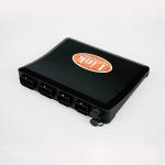
The idea is to use multiple PDMs (if needed) so that you can have your power distribution where it's used. Ie one in the front for fans, water pump etc, one in the back for fuel pumps, active aero etc. Also total current is usually the limit on most PDMs, so even with more (unused) outputs, you might need a second PDM.
Here's a FB screenshot that I thought was a good explanation.
Thats my post ;-)
- essb00 and Arron Eades
-
 2
2
-
It's really depends on your expectation how much you want to optimise your engine. The influence of inj timing differs a lot between engines. I've seen anything between 0.x% and up to 10% torque change by varying inj timing (same AFR). It does also make a good difference to the transient response of the engine and how much accel emrichment is needed. Personally I don't agree that a single value is enough. I do map all cars with full 3d injection timig table and optimise it at all and load and RPm points.
-
I would check also injection timing. Try to optimise it first before going to charge estimation table. Maybe you sit just at a inj. Timing the engine is not happy.
I usually tune in the following order:
- use a charge estimation table from a similar engine with same IAT sensor location
- tune charge cooling coefficient (sorry don't remeber exact name right now)
- roughly. Tune variable cam map than fuel map and finally injection timing arround load/rpm points you want to test charge estimation.
- run charge estimation test. Roughly adj. Fuel map after a big change to bring back Lambda to target. Test and repeat.
- once satisfied with charge estimation, start with finetunig camtiming > fuel map & inj. Timing. Finally ign timing
-
Or another possibility is to raise the knock limit alot at that specific point.
-
On 10/14/2021 at 10:59 PM, davetest said:
How are you going to keep the turbo spooled if you just cut the fuel which was being combusted to keep the turbo spooled?
You don't cut 100%
It's around 70-90% and the remaining combustion will be retarted up to 35° ATDC.
This is high effective and produce at least as much bosst with ign cut, but by fare more steady. Works for antilag and launch control.
-
If already on idle ign ctrl topic. I would like to have an idle ign target 2D table. So the target can be influenced based on ECT or running time.
-
Maybe I'missing something. But with the GP latched inputs, math counter function, Virtual Aux I don't see what couldn't be done?
-
Great idea for what the firmware is now. However I hope a proper torque control strategy which controls TPS and pre throttle pressure. Incoperating ignition amd lambda efficiency (actual vs optimal ign angle), charge temperature etc.
So the e-throttle table is just a Torque request value. Boost, TPS angle etc. is then adjusted to get the desired torque.
-
On 5/24/2021 at 11:13 PM, Adamw said:
Yeah, it used to in G4+ but it was changed in G4X. I just remembered someone else asked for this so I will check if there is any reason it needs to be that way and get it on the request list.
That one was me Adam.
For same reasom as above. Post start enrichment etc. This makes the crank and post start decay time tables absolut.
-
BTW
K-type thermocouple can directly be connected to the AIM MXS Strada analoge inputs. Then send it to the ecu over can if you need it there.
-
Normal
G4X has a different accel mode.
-
-
Update firmware!
-
Download the latest PC Link Verison on www.linkecu.com > support
-
-
15 hours ago, Adamw said:
Here is a table setup that will give you the same result as above but with no interpolation:

Other suggestion:
Set all 0 cells to 25
Set Output activation to:
ECT> 70 deg AND IAT >60deg
OR Virtual AUX X = ON
Virtual AUX X
ECT >80 deg and IAT >50 deg
OR ECT > 90 deg
This should do the job just fine. I can not think of a situation where you have IAT> 60deg and ECT< 70deg.
Btw don't see how the fan has any effect on IAT....
-
Det tj
He table higher than 25% and activation condition ECT > XX °C
-
Are you sure the right boost table is active?
-
I would no necessarly agree that pwm frequency has no inlfuence. Especially at such high frequency i'ts likely the current is not a nice square wave any more. If you zoom in with a oscilloscope the tace is looking more like a sinus curve (eges rounded). Means total energy in the coil of DBW Motor( area under the curve) is less., especially at low Duty Cycles.
This behavior can be seen already with 50hz+ on a Hella PWM Relay.


Will Force GDI upgrade to G4X
in WishList
Posted
Couldn't an external box just be used for any DI engine?