Simon
-
Posts
5,121 -
Joined
-
Last visited
-
Days Won
115
Content Type
Profiles
Forums
Events
Gallery
Blogs
Downloads
Everything posted by Simon
-
Yep spot on.
-
Yep should cover all wheel speed sensors nicely
-
Hi. Just a little concerned that you got no response from email as we pride ourselves on answering all emails with in 2 working days max. Were you emailing direct to [email protected] or putting in a form submission off the web page. If off the web page form we did have an issue where it was not sending to the tech inbox. If this was the case very sorry about the lack of reply. This issue has been resolved. Looking at the capture in the first post the polarity looks correct for both sensors. The crank dose have a couple of low teeth which if the arming voltage was set to high could cause trigger faults. The arming voltage needs to be 50-70% of the smallest peak voltage. If you want to post or email the map we can take a look at the settings. A log with VVT trying to work would be good to if possible.
-
6500Hz
-
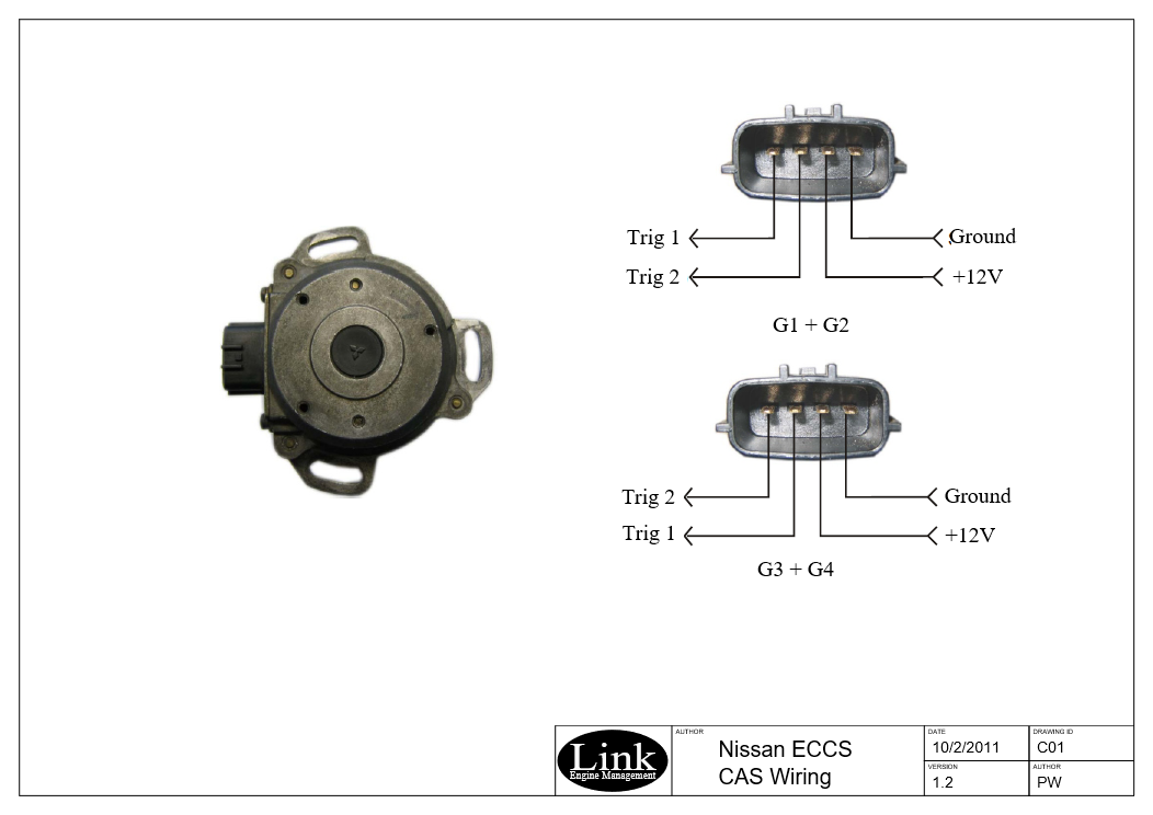
Hi there is some variation in the CAS sensor. The late R34 sensors are a mirror image of the attached image. I don't have a pinout for the coils.

-
The narrow band setting will be the one to go for. This will give the clearest noise increase if knock should occur. Frequencies outside will be suppressed but if they were loud enough can still get through to some extent.
-
Trigger two polarity is incorrect. Signal and ground connection need to be swapped. What are you triggers settings set as? I have seen a 0RPM reading when the trigger 2 mode is set to cam level. This would be incorrect for this application. Triggers should be set as below.

-
You will need an additional condition. For example you might switch to table 3 if Di is active and Nos is on. To do this you would use a virtual aux as the condition for the table. You are not able to use a single Di to select more than 1 table.
-
No as the board that is installed is geared for a Reluctor sensor not the optical that the Nissan has.
-
Stock disk will work with the Nissan Sub-board.
-
No as the hardware required is different. The G4+ uses a different micro with different footprint.
-
Fire it through to [email protected]
-
Few things to check. Make sure the fault settings on the AN volt inputs are clear of the voltages being seen from the throttle. On the Toyotas the TP sub will only span to about 70% of the main which will cause issues so will need to use the TP main signal to feed both inputs. (G4+ fixes this) Check throttle moves in correct direction when doing the calibrate it should close then open fully. IF you start with lowish PID figures it should be enough to do the cal process and then you can refine them later.
-
When you are in the reply window click on the choose files link in the bottom left of the window.
-
That's a G4 plugin which is based on the Storm so you will only have 6 digital inputs available. Whatever is displayed in PC link is the total amount of available inputs or outputs.
-
It would be good to get the latest firmware in there just in case. But I don't know of any previously found odd fire bugs. The main issue around odd fire originally was that we couldn't do it in a wasted spark format.
-
If the Di's are not displayed then the ECU have does not support them. This can be the case where a bottom board has had the extra inputs added to allow for future top board developments.
-
Would have to check inside the ECU but very likely its set for the stock 1gg If you were able to post a photo inside the ECU we can confirm.
-
Does it move slowly up or does it do it in a jump? And is it a fault that has developed or one that might have always been there?
-
Generally the best result is obtained using TPS for the main fuel axis. You would initially just set with the "init" values which will give 10% steps 0-100% Then have the open loop AFR table on and set to MGP of its axis this will give boost correction.
-
Hi Jonathon The store will be taking place ok. This was a firmware issue a while back. One option is to update the firmware the other just leave as is. You will find that if you cycle the key and reconnect the changes made will have been saved.
-
The pinout would match a 3 channel bosch igniter with the 7 pin plug but not the one you have shown. See attached. I3.pdf
-
Attached files should be what you are after. LinkPlusbook.pdf CA18DET, SR20 DET F&I L+.pdf
-
Yes that is no problem to do. For high impedance injectors only change needed will be to reduce the fuel master to get the mixtures correct. If using low impedance the peak and hold currents will need to be adjusted to suit the currents required for the paired injectors.
-
That part matches the QG18 the cam has 4 groups of teeth 3teeth, gap, 4 teeth, gap, 2 teeth, gap, 1 tooth