


Vaughan
-
Posts
2,117 -
Joined
-
Last visited
-
Days Won
74
Content Type
Profiles
Forums
Events
Gallery
Blogs
Everything posted by Vaughan
-
I've also just increased the range in which the gear ratio is considered stable so the automatic calibration of gear ratio should work better in the next release.
-
Not all pins on the ECU are exposed, most vehicles only need a small subset to perform all the factory operations and more. On the WRX107+ An Volt 12 and Aux14-16 are not exposed but if you need more pins than you have exposed we can add a connection to these pins (read soldering on some flying leads). Typically this is a send back to have the servicing guy do this kind of thing.
-
When using a Monsoon you should have an 'Internal' option in that Source selection list. If you are making your monsoon basemap out of one of the sample honda maps and you haven't connected to the ECU then the basemap will still think it's a plugin and so won't show the 'Internal' option. To make the basemap offline you will need to start with the sample Monsoon map and go from there.
-
If you are using a direct spark ignition setup and it has the disk with 5 equal gaps and one large you will need to change the disk for it to work properly in the 360 opto mode. Are the TB48 all direct spark from factory? You should be able to check your disk style by cranking it over and performing a trigger scope.
-
If the idle got rougher and it is showing a leaner afr it seems reasonably likely that it is missing which causes a leaner afr (sensor measures how much unburnt oxygen there is).
-
With the 360 opto mode in G4X it looks at the ignition mode and the number of cylinders to determine the trigger 2 tooth pattern so I would recommend against changing between distributor and non distributor disks if you are not changing your ignition system too. The G4X should sync faster than the G4+ but you still require enough crank etc enrichment to make it fire quickly. If you do change the trigger disc without changing the ignition system you can use the 360 opto widest slot mode but this mode will not sync as quickly as the regular 360 opto mode.
-
Use the logged value
-
go for a short drive while logging the gear ratio calc runtime value, when you look at your log you should see 5 (or 6) defined steps in that runtime, highest step value is gear 1, lowest is your top gear, set the gear detection type to user defined and enter those values into your table. I'll fix that bit of help up and do some more investigation of the software. Think it can get a bit confused if the values in the table aren't consistently getting smaller from right to left.
-
if you connect new wires to the O2 signal and heater pins then they can indeed be used as a spare An Volt and Aux respectively. But if you are going to do this you may as well add new CAN wires and reuse the existing O2 wiring for your Analog and Aux functions (unless you are using your analog and aux in the cabin in which case you don't have to run the wires through the loom to the engine bay).
-
GP Outputs and GP PWM Outputs don't display the rest of the settings until an output is selected. Do you have a screenshot of a GP Output with an output set but no settings showing?
-
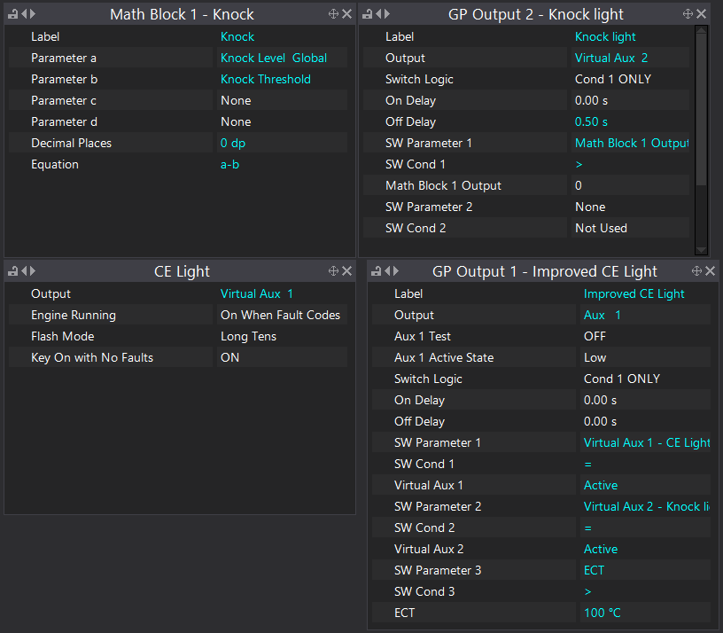
Something I've done recently is add a knock warning to my CE Light, I used a math block to calculate knock level - threshold and put it through a gp output to get an off delay (hold time) and fed it into the CE Light Aux. So far I've only used it for playing around with setting up my thresholds (so I can see how often it happens and for a clearer picture of when it happens) but I imagine it will be very useful once I've finished setting u the knock too. It has also been very useful for reviewing Knock stuff in PCLink logs as often the knock stuff happens too fast to be caught by PCLink but the knock light status can be used to see when it occurs without needing to actually see the knock level above the threshold.
-
The CAN Lambda CAN info is in the help manual under G4X ECU Tuning Functions > CAN > Device Specific CAN Information which includes what CAN info it receives and transmits as well as how to configure the CAN Lambda. Yes the CAN Lambda will work with other brands of ECU as it only requires a simple CAN setup, you might need to setup custom transmit and receive streams in the ECU you are using (Only receive is needed but transmit allows exhaust pressure correction and stops it from starting until after the engine has). The sample rate of the Lambda value is 100Hz and the delay between the engine's afr changing and seeing that change is mostly dependent on how far the sensor is from the cylinders.
-
On the G4X if the Lambda value is above 9 or below 0.1 CLL will not run. Also a map or tps delta value of 0 means no map or tps delta lockout. Max tps lockout value is 0 but the tps value has to be greater than this value to hit the lockout and tps cannot be greater than 100%.
-
Yup, will be common with ISC stuff and other 12v supplies in the loom. They cannot, CAN requires special differential hardware, they would need to be wired to one of the CAN plugs on the bottom board (same plug style as the expansion loom but only 5 pins). Also I would de-pin if possible rather than cutting but either will work. Typically they are twisted around each other but if you are disassembling the loom enough to twist or wrap the full length you may as well as well just run a fresh pair of wires instead of reusing the O2 sensor ones. Just an earth wire to the chassis, CAN uses a differential signal and so doesn't need a reference earth, this earth is for powering the CAN Lambda unit and part of that control involves putting a large amount of current through the wideband sensor heater coil and so using one of the ECU Signal earths could damage the ECU. No problem, happy to help.
-
Looks like it is a 3 wire sensor which is most likely a 12V, a switched heater ground (typically Aux 7) and the signal which is connected to An Volt 1. To repurpose these for a CAN Lambda you would use the 12V for CAN Lambda power (check that it is ign switched), cut or de-pin the An Volt 1 and Aux 7 wires at the ecu and use them for CANH and CANL and add a ground to the chassis in the engine bay for the last CAN Lambda pin. The risk with doing it this way is you could end up with a lot of noise on the CAN bus as Heater ground and signal wires aren't twisted around each other or shielded from the rest of the loom.
-
That actually looks like my bad, CAN Aux aren't quite ready yet and I made sure their settings didn't exist in the release but I have managed to leave them as options that can be selected, please ignore them for now. If you try and use them now you'll probably need to turn them off and back on again once the actual functionality is released
-
Yes you still need to do the map calibrate, the map calibrate checks to see if the map reading is within 5kpa of the baro reading and then slaps an offset on it to make them match. What pressure value does it show for MAP and what voltage value does it show for the Analog voltage (should be An Volt 3) when you have the link sensor connected? The 1kOhm (Internal) and 10kOhm (Internal) settings change the size of the internal pullup resistor used, this setting is usually changed to improve the resolution of the sensor around the area you expect it to operate in. The temperature calibrations are stored as a resistance per temperature so the ECU can calculate the resistance of the sensor by treating the system as a voltage divider with a constant value resistance from 5v to the ECU channel and a varying resistance from the ECU channel to (signal) ground. Temperature sensors typically don't change resistance relative to temperature linearly so at one end of it's range there are large changes of resistance for small temperature changes and at the other end there are small changes in resistance for large changes temperature.
-
what is the status of the idle ignition control when it is not responding to the idle ignition values? It is probably in a lockout of some form.
-
The help manual has a section on the dash2pro and the attached dash configuration file will be in the next release DASH2PRO.CMG

-
try it with a divider value of 10000
-
Open loop is active all the time, Speed lockout turns off Closed loop I believe
-
coworker has made the comment that you might be better of switching around math block 1 and 2 there as that would mean the LH End calculation would happen immediately before the lower threshold calulation which uses it instead of using the value from the last round of calculations, I doubt you would be able to see a difference but it would be more technically correct.
-
Try this, seems to work from a quick play on the desk

-
they shouldn't be throwing fault codes if they are connected to the ecu regardless of whether or not the engine is running, what voltages do they show with the sensors connected and what do you have set as the error low and error high values? Also don't forget to clear the fault codes once you think you have solved the problem as they don't go away on power cycle
-
yes it is, it isn't possible to do direct spark without adding a cam trigger signal though.


