


Vaughan
-
Posts
2,117 -
Joined
-
Last visited
-
Days Won
74
Content Type
Profiles
Forums
Events
Gallery
Blogs
Everything posted by Vaughan
-
Just the image save removed, the log is much better than an image to deal with
-
My Stagea uses a calibration value of 530 if that helps, RSFourS box (R33 GTR) 4.33 diffs I believe and 225/55R17s with the speed signal coming straight from the box. It is possible to calculate it all out but will be difficult with a VR sensor as you can't easily count the number of teeth per rotation. From the help manual, you may be able to correct for diff ratio

-
it would fire the ignition and the injector once per engine cycle not 4 times
-
you would probably setup the fueling to be single point group with active drives set to 1-2 (only wire up injector drive 1), the only way to use only 1 injector at the moment is sequential injection on a 1 cylinder engine. Scope of the trigger pattern is best as it shows the number and shape of the teeth as well exact positions and widths. Might be worth checking the resistance of the injector and seeing if it has a resistor pack.
-
That setting is the base timing, you have to set it from within the calibration window (when the window is open it forces ignition timing to a constant value). Having fuel off is recommended when setting the base timing but you need to have ignition on to set the base timing as you are comparing the ignition signal timing to the engine position. 1 or 2 trigger errors when you stop cranking doesn't surprise me, it is expecting another tooth but it never occurs because the engine stopped spinning. If the trigger error keeps counting up continuously that would indicate you have a real issue.
-
My motor is a modified 2006 Aurion and I used Bank 1 (the rear bank) inlet cam for my Trigger 2 signal, your trigger scope matches mine. You should be able to check the trigger offset while cranking it over and your attached triggerscope file looks fine with no obvious issues (the triggerscope only logs a small number of runtimes). Do you have a normal log of the engine cranking? Looking through your basemap I would recommend trying a trigger offset more like mine (-356), it looks like it is currently set to 0 in your map. Also both your fuel and ignition are off in that basemap
-
Bit hard to say without a copy of the log, I would recommend tuning your fuel table correctly rather than relying on the CLL to catch it, at the very least make it rich under load and have the CLL removing the unnecessary fuel.
-
If you get rid of the dedicated AC VSV you can just adjust the AC Offset Table and the AC Idle up setting to change the IACV Position and the target idle speed respectively when AC is turned on, adjust these values so that the closed loop control doesn't have to respond to it because it has been taken care of by the open loop values.

-
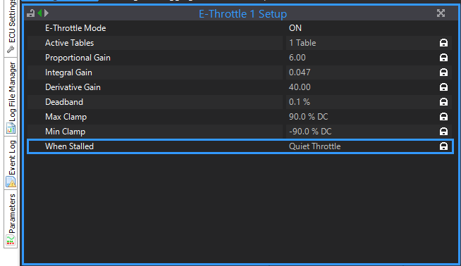
Could you attach a log of everything powered up with accelerator pedal being moved please Actually one quick note is that you have it set to Quiet throttle when stalled so if you are testing with the engine off the throttle won't move. You also have an ethrottle fault recorded so not a bad idea to clear your fault codes and see if that returns.
-

Series 4 RX7 Can’t hold idle, Link Monsoon G4X
Vaughan replied to HaveYouSeenAWizardSleep's topic in G4x
That log shows it running incredibly rich, try bringing it back closer to your target afr -

-
That track controls the ECCS Relay
-
You don't appear to have an ISC valve setup and so are only using ignition idle to control the idle speed. Looks like it's not dropping below the Idle Ignition RPM Lockout and so the ignition idle control never pulls the ignition angle (and as a result engine speed) down. Maybe try reducing the ignition table values in the idle area of the table.
-
In terms of fueling that tune is factory FE injectors with a 400kpa returnless Fuel system (pressure doesn't change with manifold vacuum)
-
I'm not a professional tuner and I am still playing around with various aspects of the tune so don't take any of this tune too seriously. This file is also about 3 months old and from memory was running too rich under full load and high rpm. 2GR-FE with aftermarket cams, valve springs and 11:1 forged pistons2GR MR2 Trackday.pclx
-
This was spotted fairly quickly and a new version was put up with a fix (6.18.32), another version with language support (6.18.44) has also been put up since that so grab the latest PCLink and firmware please and let me know if it's still a problem. Thanks
-
Worth a shot, we tested my sensors on the desk to find the ideal value, from memory the G4+ and G4X have different trigger hardware
-
it will effectively average the CLL over time by incrementing when CLL says more fuel and decrementing when CLL says less fuel for each cell in the LTT table/s. Yes the LTT value is added to the fuel value as a percentage so a LTT value of 2 and VE (Fuel Table) value of 80 would act the same as a VE table value of 81.6 and a LTT value of 0. Over time the CLL values should become closer and closer to 0 assuming you have all engine paramters covered, if you aren't correcting for something (say IAT) then you will see different CLL and so different LTT values at different times. If you do see your LTT values increasing some days but decreasing other days in the same cells then you need to look into what could be affecting the engine that hasn't been accounted for.
-
Use the CAN Test calculator function in the CAN Setup window to see what to multipliers and offsets different runtimes have
-
You could probably use a relay to supply power to the cars ignition switch on circuit in the same way aftermarket turbo timers do but you will have to use a GP Output and timer as ECU Hold Power applies an engine kill and you will have to consider that you might back feed power to the rest of the car depending on everything is wired up. I would also recommending wiring up an engine kill switch which either turns off the relay or tells the ECU to kill the engine as a safety feature.
-
R34 GTR was compared against the display that they have, my Stagea (WGNC34 Series 1 wih RB25DE S2 motor and auto box, Grey Plug ECU but not a NEO) had a 1:1, if you want to be sure for a particular car would be best to check with the factory computer and a multimeter with the engine off. I think I may have heard that there is a difference between auto and manual so any additional information to add to the manual would be helpful. using 2:3 instead of a 1:1 on a 1:1 car will result in a lower tps signal which should theoretically mean less power to the front wheels but the factory accelerometer/s signal might result in 50:50 in that situation anyway.
-
For the logs being split up, what are your activation settings for your ECU Logging? The triggerscope was loading the layout on filename alone, have changed it to explicitly use the directory of the executable, will be in next release. Looking at the picture of your log those aren't real values so either the log file on the ECU is corrupt or it has had a serious issue while downloading it to the computer.

-
That looks to be my bad, An Volt 7 is on D25
-
Has it previously worked? Latest PCLink and Firmware? Is PCLink installed in a weird location? Are you running PCLink from a different directory (such as calling the executable from the command line)? One way this can happen is if the shortcut's "Start in" location is wrong.

-
do you have a "TSViewlayout" and "TSViewLayoutM" file in your PCLink install directory?


