


essb00
-
Posts
367 -
Joined
-
Last visited
-
Days Won
5
Content Type
Profiles
Forums
Events
Gallery
Blogs
Everything posted by essb00
-
Tach driven by Aux 4 instead. Shift light to Ign 3 (active low). Speedometer driven directly by VSS -- Ign 4 unused.
-
As what Adam already mentioned, most probably the Link 7 bar calibration table is off compared to what is supposedly used for your fuel pressure sensor. Wasn't there any calibration points/table provided when you purchased the sensor? Are the injector dead times you've there, the ones provided with the injectors? What's the impedance/resistance of the injector coils as measured? About your IAT, you should fill out some values on your 'Charge Temperature Approximation Table'. Refer to the help file for some guidance.
-
Pls attach your latest tune file so we can see how you configured the calibration table for the LC-2. 14point7 Spartan 2 is one good gaugeless analog wideband controller. The Spartan 3 has CAN. If you only have 1 lambda controller connected (assigned as Lambda 1, nothing assigned on Lambda 2), then you should only look at Lambda 1.
-
Just to clarify, your fuel system is return-less -- pressure regulator no MAP reference? Where do you have the fuel pressure sensor installed?
-
Hi... Update your ECU firmware to the latest version. There, you'll see a CEL Mask table where you can mask certain error codes. *Change the value from 0 to 1 to mask.

-
Although your Trig 1 voltages seem low, they appear to be clean in all the scopes you have attached - so it will be fine. ...but yeah, it would be nice to have another dizzy just to compare and to have it as spare.
-
Yeah... there, for some reason your Trig 1 voltage is lower than other 4A-GE stock triggers I have encountered -- where your Trig 1 voltage peaks touch below the arming threshold. Adjusting the trigger arming threshold (as per attached below) should remedy that, but try to adjust the gap/clearance of the NE pickup to the teeth. If I remember correctly minimum clearance as per repair manual should be 0.4mm.

-
ECU turns off fuel & ignition whenever it loses the engine position due to unstable/unreliable trigger signals. Could you again take trigger scopes, perhaps on idle and another around 2krpm?
-
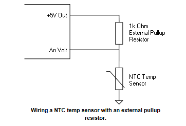
You can connect additional temp sensors into AN Volt Input - you have to connect a 1KOhm external pullup resistor. On the still unused Analog Input, select 'GP Temp (Ext Pullup)'. Then select the calibration table you have set for the sensor you installed.
-
The dips/peaks seem acceptable. Do you have closed loop idle control on? I'm just trying to guess what you got as you didn't attach your tune file. If you have the Engine Fan controlled by ECU (triggered by one of the outputs), you can have the 'Engine Fan Idle Up' setup. Sample attached 'Alt Control Target Table' should cover your intended targets for overrun, idle, cruise, & full throttle -- adjust the values as you want them to be.

-
You might just need to make adjustments on the 'Alternator Control' PID to make it more responsive to changes in charging voltage. 'Alt Control Target Table' you can also change to 3D so you can have another parameter as qualifier for your target voltage. As the idle speed is a big factor for alt charging, have you already maximized the following? Engine Fan Idle Up Power Steer Idle Up Gear/Drive Idle Up GP Idle Up AC Idle Up *Most of the above can be assigned to a 'Virtual Aux' that could be triggered by multiple parameters/sources (depending on conditions you set on 'GP Input'). 'Idle Base Position Table' and 'Idle Target RPM Table' can also be changed to 3D with your choice of another parameter on the Y-axis.
-
'First Crank Prime' is just a percentage added to the 'Crank Enrichment' value on first engine rotation (whenever ECU has already detected the trigger sync tooth). You should be able to see the difference in the logged 'Injection Actual PW' during cranking whenever you would change the 'First Crank Prime' percentage.
-
AFAIK, only the the AltezzaLink Plugin ECU has the electronics to convert CAN bus data to the Toyota proprietary data bus, so the Altezza gauge cluster would not work with a Monsoon (I also thought about this before, but not possible). Speed sensor you can connect to a DI so it can be viewed/logged in PCLink.
-
Depending on engine setup, the effect of default engine limiter cuts would be different. To change the Start Cut & Cut Decay Time, you need to enable the Advanced Mode. See help file for info on how to set it up (you may be needing to do some trials to get your intended outcome).

- 14 replies
-
- 1
-

-
- rpm delay
- altezzalink
- (and 1 more)
-
Just as I thought... but it is not clear on the picture how many teeth were ground off... Does all the teeth left have the same heights? What's the air gap to the pickups?
-
...24 teeth on trig 1 CAS? Your triggerscope result does not seem to correspond to any 'stock' CAS pattern of 4A-GE... Can you try another triggerscope?
-
Could you confirm (perhaps take a picture) how many teeth in the CAS inside the distributor? Some early 16V 4A-GE (for trig 2) has 4 teeth, later 16V has only 1 tooth.
-
Well, it is really hard to tell what's going on as you don't have wideband o2 sensor connected yet on the logs. ...but correct the following on the screenshot below. *Fuel system type = MAP referenced (as you don't seem to actually have an FP sensor installed). Injector rated fuel pressure = try 300kpa (this is the usual manufacturer reference fuel pressure on the given flow rate).

-
Have you confirmed if your COPs are wired correctly in order of Ign1 to cyl 1, etc. If they're ok, next step is use a timing light as Adam mentioned to confirm if the ignition fires with the pulley TDC marker aligned to 10° BTDC on the timing belt cover. On my 4A-GE 16V with stock 250cc injectors, (cranking) injector pw is around 14ms (about 30°C ECT/IAT)... Yours is commanding (cranking) injector pw 16ms with 440cc injectors which I think is way too much. Try to put 12ms master fuel. ...or perhaps change it to modelled (enter your injector details in injector setup), then use my fuel table (not fully tuned) below. Fuel Table 1.lte
-
It just realized that it is based on my old-old map... It still has my engine number on the VIN in configuration page. Anyway... 1. Try to verify the order of wiring for each of your COPs. 2. Fuel table is for 'modelled', so having to use it for 'traditional' would really make your engine flood. 3. Then also, you might have to make adjustments on your dwell control table (my stock ignition was just triggering CDI box, that's why I can keep the values low on the dwell control table). Try the attached table. Ignition Dwell Control (ms).lte
-
Try Spark Edge: Falling

-
Your trigger 2 is noisy and the noise are touching the arming threshold voltage. Could you check how much is the air gap? It should be minimum 0.4mm for 4A-GE stock CAS. Try to up the Trig 2 arming threshold to 0.3V for 500rpm on your table. Also, did you use G1 or G2 for Trig 2? If you used G2, trigger offset should be correct. If you used G1, try trigger offset 352.
-
The speed reading spikes are caused by high frequency noise being picked up by the DI. Try this simple low pass filter circuit below (just if you have some electronic parts lying around). This solved similar problem on mine (though on G4x).

-
what type of speed sensor do you have connected to it DI 3? Reed switch from gauge cluster?
-
If you didn't also change the fuel table, then it won't work with modelled fuel equation mode -- as the numbers on the fuel table has to be VE (volumetric efficiency). Double all the values in your fuel table as you shift to modelled, perhaps it would be enough to make it start -- but you'll be having to tune the full fuel table again in modelled mode.


